15 • Wiring the Beacon 800 Gas Monitor Beacon 800 Gas Monitor Operator’s Manual
Connecting External Alarms
Perform the following procedure to connect external alarm devices to the Beacon 800.
NOTE: The alarm terminal strips include terminals that are dedicated to individual
channels and levels of alarm. The controller terminal strip includes terminals for
common alarms (dedicated to all channels).
The example used in this procedure describes connecting an external alarm
device to the channel 1, alarm 1 terminals on the alarm terminal strip.
WARNING: Do not connect external alarms to the 24 VDC terminals.
1. Locate the applicable alarm terminal strip (see Figure 1 on page 4).
2. Install an appropriately rated cable bushing or conduit in an unused conduit hub on
the bottom of the Beacon 800.
CAUTION: Only use the four factory installed conduit hubs on the bottom of the housing
for wire entry into the housing. Do not drill the housing for any reason. See
“Routing Wiring Into the Beacon 800 Housing” on page 12 for more
information.
3. Guide the wiring of the external alarm device through the selected conduit hub on the
bottom of the Beacon 800 housing.
CAUTION: Do not route the external alarm wiring and detector head wiring through the
same conduit hub. The external alarm wiring may disrupt the transmission of
the detector head signal to the Beacon 800.
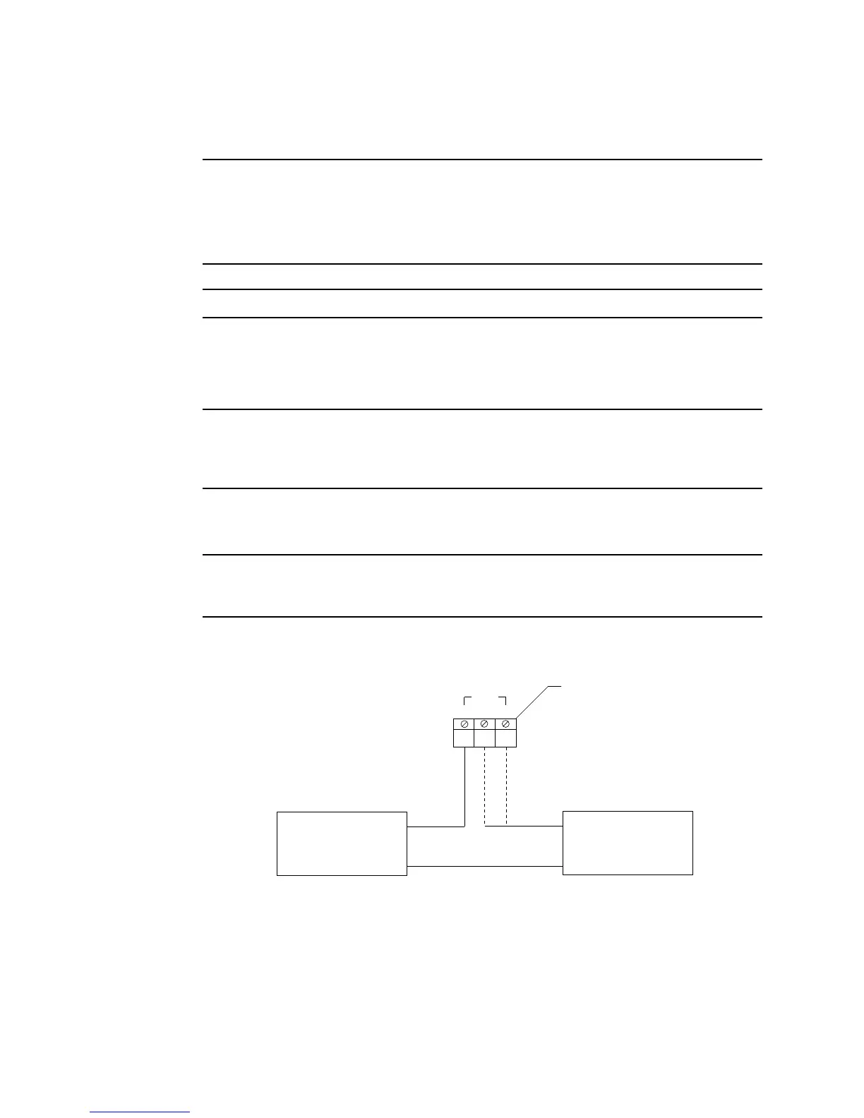
4. Connect the leads from the external alarm device to the alarm terminal strip as shown
in Figure 8.
Figure 8: External Alarm Wiring
5. Repeat steps 3 and 4 for additional external alarm devices.
Beacon 800
Alarm Terminal Strip
External
Alarm Device
(H) +
(N) -
CNONC
CH1
External
Power Source
(H) +
(N) -