17 • Wiring the Beacon 800 Gas Monitor Beacon 800 Gas Monitor Operator’s Manual
Connecting User-Supplied 4 - 20 mA Transmitters
The Beacon 800 may be used with a user supplied 2-wire or 3-wire 4 - 20 mA transmitter
which runs on 24 VDC nominal (the Beacon 800 supplies 28VDC). When this is done, the
Beacon 800 is normally setup at RKI Instruments with the following channel parameters:
unit of measure, item name, and full scale. For example, “PSI AIR” with a full scale of 10
PSI.
Perform the following procedure to connect a 4 - 20 mA transmitter, which you supply, to
the Beacon 800.
1. Turn off power to the Beacon 800 at the power source.
2. Open the Beacon 800 door and turn off the power switch.
3. See the transmitter’s instruction manual for instructions on how to connect wires to the
transmitter.
4. Install an appropriately rated cable bushing or conduit in an unused conduit hub on
the bottom of the Beacon 800 housing.
CAUTION: Only use the four factory installed conduit hubs on the bottom of the housing
for wire entry into the housing. Do not drill the housing for any reason. See
“Routing Wiring Into the Beacon 800 Housing” on page 12 for more
information.
5. Route the wires from the transmitter through the selected conduit hub into the Beacon
800.
6. Connect the wires from the transmitter to the appropriate transmitter terminal strip.
See the transmitter instruction manual for controller terminal connections.
CAUTION: Do not route power and transmitter wiring through the same conduit hub. The
power wiring may disrupt the transmission of the transmitter’s signal to the
Beacon 800.
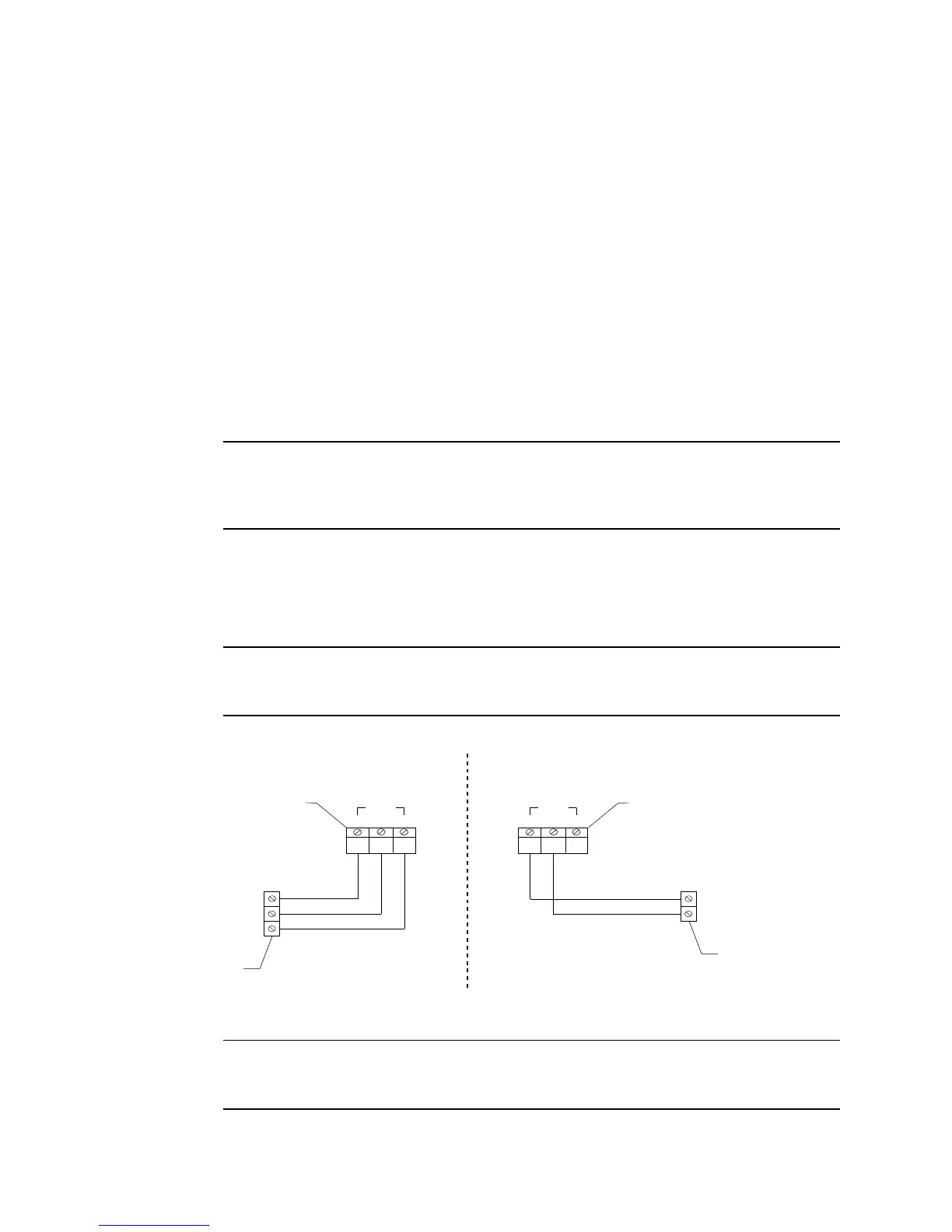
Figure 9 below illustrates typical transmitter wiring connections.
NOTE: If your Beacon 800 includes the recorder output board or heavy duty relay board,
see “Chapter 7: Optional Recorder Output Board & Heavy Duty Relay Board” on
page 34 for wiring instructions.
Beacon 800
Transmitter Terminal Strip
-
FB
Transmitter
3-Wire Connection
+
+S-
CH1
(24 VDC)
(4 - 20 mA)
(DC Ground)
Beacon 800
Transmitter Terminal Strip
2-Wire Connection
+S-
CH1
FB
Transmitter
+
(24 VDC)
(4 - 20 mA)
Figure 9: Generic 4 to 20 mA Transmitter Output Wiring