Beacon 800 Gas Monitor Operator’s Manual Heavy Duty Relay Board • 40
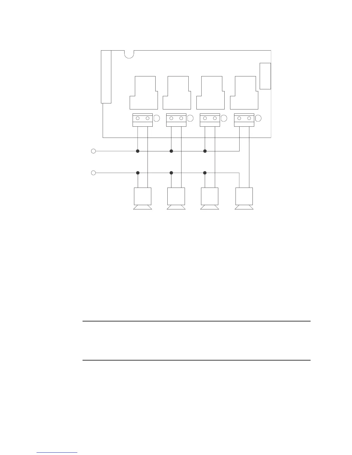
Figure 16: Wiring the Heavy Duty Relay Board
8. Rotate the display board back to its original position and secure it to the standoffs with
the two thumbscrews.
9. Start up the Beacon 800 as described in Chapter 3.
Operation
Unlike the Beacon 800’s standard relay contacts which are form C (common, normally
open, and normally closed contacts) the heavy duty relays are form A (common and
normally open). Form A contacts are open when the relay is de-energized.
The alarm conditions under which the heavy duty relays activate are programmed in the
Configuration Menu (see below). When an alarm condition occurs which has been defined
to cause a particular relay to activate, the relay contacts will change condition. They will
either open or close depending on how the relay is programmed.
NOTE: The LED to the right of each contact terminal strip indicates when the relay is
energized and the contacts are closed, not when an alarm condition has
occurred. If a relay is programmed to be normally energized, then the LED for
that relay will be on during normal non-alarm operation and turn off if the
appropriate alarm condition occurs to activate that relay.
If a relay is programmed to be NDE (normally de-energized), the contacts are open and
the LED for that relay is off during non-alarm operation. If the appropriate alarm condition
occurs, the contacts are closed and the LED is on.
If a relay is programmed to be NE (normally energized), the contacts are closed and the
LED for that relay is on during non-alarm operation. If the appropriate alarm condition
occurs, the contacts are open and the LED is off.
Heavy Duty Relay Board
(Installed in Beacon 800)
1
2
34
TB5
Alarm Device
Power
Alarm Devices