Mounting and wiring
BK52x0 and LC5200 21Version: 2.0.0
1. Carefully pull the orange-colored lug approximately 1cm out of the terminal to be disassembled, until
it protrudes loosely. The lock with the mounting rail is now released for this terminal, and the terminal
can be pulled from the mounting rail without excessive force.
2. Grasp the released terminal with thumb and index finger simultaneous at the upper and lower grooved
housing surfaces and pull the terminal away from the mounting rail.
Connections within a Bus Terminal block
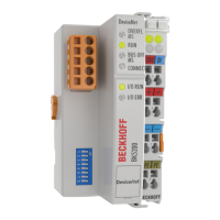
The electric connections between the Bus Coupler and the Bus Terminals are automatically realized by
joining the components:
• The six spring contacts of the K-Bus/E-Bus deal with the transfer of the data and the supply of the Bus
Terminal electronics.
• The power contacts deal with the supply for the field electronics and thus represent a supply rail within
the Bus Terminal block. The power contacts are supplied via terminals on the Bus Coupler.
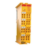
Power contacts
During the design of a Bus Terminal block, the pin assignment of the individual Bus Terminals must
be taken account of, since some types (e.g. analog Bus Terminals or digital 4-channel Bus Termi-
nals) do not or not fully loop through the power contacts. Power Feed Terminals (KL91xx, KL92xx
and EL91xx, EL92xx) interrupt the power contacts and thus represent the start of a new supply rail.
PE power contact
The power contact labelled PE can be used as a protective earth. For safety reasons this contact mates first
when plugging together, and can ground short-circuit currents of up to 125A.
NOTE
Risk of damage to the device
Note that, for reasons of electromagnetic compatibility, the PE contacts are capacitatively coupled to the
mounting rail. This may lead to incorrect results during insulation testing or to damage on the terminal (e.g.
disruptive discharge to the PE line during insulation testing of a consumer with a nominal voltage of 230V).
For insulation testing, disconnect the PE supply line at the Bus Coupler or the Power Feed Terminal! In or-
der to decouple further feed points for testing, these Power Feed Terminals can be released and pulled at
least 10mm from the group of terminals.
WARNING
Risk of electric shock!
The PE power contact must not be used for other potentials!
Wiring
Up to eight connections enable the connection of solid or finely stranded cables to the Bus Terminals. The
terminals are implemented in spring force technology. Connect the cables as follows:
1. Open a spring-loaded terminal by slightly pushing with a screwdriver or a rod into the square opening
above the terminal.
2. The wire can now be inserted into the round terminal opening without any force.
3. The terminal closes automatically when the pressure is released, holding the wire safely and perma-
nently.
Shielding
Analog sensors and actuators should always be connected with shielded, pair-wise twisted cables.