List of figures
BK52x0 and LC5200 45Version: 2.0.0
List of figures
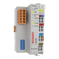
Fig. 1 BK5200 – Bus Coupler for DeviceNet ......................................................................................... 8
Fig. 2 BK5250 – Compact Bus Coupler for DeviceNet .......................................................................... 9
Fig. 3 LC5200 - Low-cost Bus Coupler for DeviceNet ........................................................................... 10
Fig. 4 Principle of the Bus Terminal....................................................................................................... 14
Fig. 5 DeviceNet .................................................................................................................................... 15
Fig. 6 Example of DeviceNet in use....................................................................................................... 15
Fig. 7 Data exchange............................................................................................................................. 17
Fig. 8 Overview of the identifiers used................................................................................................... 18
Fig. 9 Spring contacts of the Beckhoff I/O components......................................................................... 19
Fig. 10 Dimensions .................................................................................................................................. 20
Fig. 11 BK5200, BK5210, BK5250 – potential groups............................................................................. 23
Fig. 12 Potential levels of the BK5200 and BK5210 ................................................................................ 24
Fig. 13 DeviceNet connection – pin assignment...................................................................................... 25
Fig. 14 LC5200 - Connection diagram..................................................................................................... 25
Fig. 15 DeviceNet – Baud rate and bus length ........................................................................................ 26
Fig. 16 Layout of the ZB5200 CAN/DeviceNet cable............................................................................... 26
Fig. 17 Cable assignment ........................................................................................................................ 27
Fig. 18 Start-up behaviour of the Bus Coupler ........................................................................................ 31
Fig. 19 Output data in the Bus Coupler ................................................................................................... 32
Fig. 20 Input data in the Bus Coupler ...................................................................................................... 33
Fig. 21 Process image in the BK5200 and in the PLC (scanner) ............................................................ 33
Fig. 22 BK5200 - Configuration ............................................................................................................... 35
Fig. 23 DIP switch.................................................................................................................................... 35
Fig. 24 Process image in the Bus Coupler – output data ........................................................................ 43
Fig. 25 Process image in the Bus Coupler – input data........................................................................... 43