Mounting and wiring
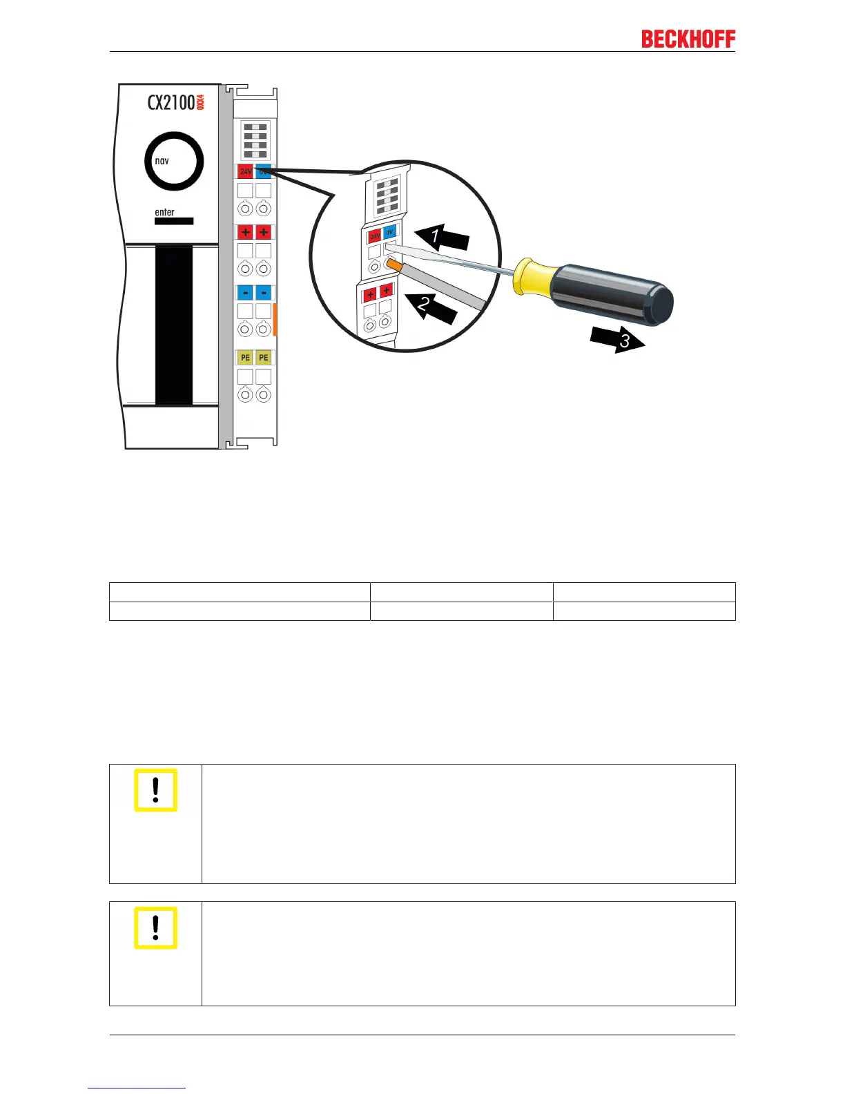
The terminals are implemented in spring force technology. Connect the cables as follows:
1. Open a spring-loaded terminal by slightly pushing with a screwdriver or a rod into the square opening
above the terminal.
2. The wire can now be inserted into the round terminal opening without any force.
3. The terminal closes automatically when the pressure is released, holding the wire safely and
permanently.
Wire cross section 0,5 ... 2.5 mm
2
AWG 20 .. AWG 14
Strip length 8 ... 9 mm 0.33 inch
LED
If the power supply unit is connected correctly and the power supply is switched on, the two upper LEDs in
the terminal prism are green. The left LED (Us) indicates the CPU supply. The right LED (Up) indicates the
terminal supply. The other LEDs indicate the Terminal Bus status. A detailed description of the LEDs can be
found in section “LED troubleshooting”.
PE power contacts
Attention
Power contact “PE”
The “PE” power contact must not be used for other potentials. “PE” and “0V” (24 V system
supply) must be at the same potential (connected in the control cabinet). The cabling in the
control cabinet must be done in accordance with the standard EN 60204-1:2006 PELV =
Protective Extra Low Voltage. EN 60204-1:2006 section 6.4.1:b: one side of the circuit or
one point of the energy source of this circuit must be connected to the protective conductor
system.
Attention
Interruption of the power supply / switching off
The device may not be switched off by disconnecting the ground. The 24 V line must al-
ways be disconnected, as otherwise current may continue to flow via the screen depending
on the device. Any connected devices with their own power supply (e.g. a panel) must have
the same potential for “PE” and “GND” as the CX system (no potential difference). Other-
wise damage can occur both to the controller and to the periphery.
CX2100-09x434 Version: 1.3
 Loading...