Product overview
CX9000 / CX901018 Version: 2.6
Table2: Assignment of the RJ45 interface, Port 2:
PIN Signal Description
1 TD + Transmit +
2 TD - Transmit -
3 RD + Receive +
4 connected not used
5
6 RD - Receive -
7 connected not used
8
TD & RD are exchanged at the hubs or between two PCs.
Connection of the Ethernet ports:
Attention
Ethernet ports
The two Ethernet ports of a basic CPU module must not be connected to the same external
switch!
Note
Only for LAN
Only for use in LAN, not for connection to telecommunication circuits.
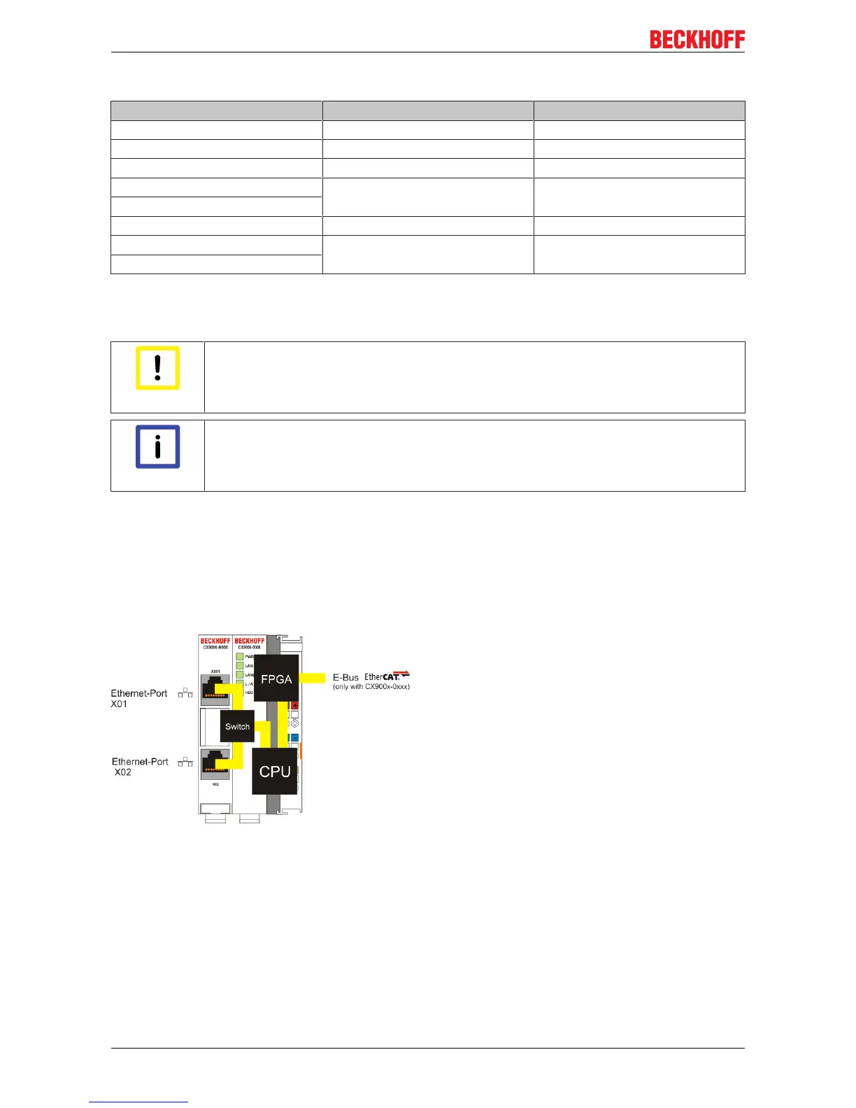
Schematic structure of the network components:
The CX90x0 features two MAC blocks. The first one (MAC1) operates the network interfaces for the Ethernet
ports. The two outputs are connected via a switch. In this way a line structure can be configured as
described below. From an operating system perspective this represents a single connection. The second
block (MAC2) operates the extended PC104 bus. The second physical network connection is used to run the
E-bus connection. (in version CX900x-0xxx) The signals are connected to and FPGA. This unit converts the
Ethernet signals to E-bus signals. So EtherCAT terminals can be connected to the system.
If K-bus is used as terminal bus (CX900x-1xxx), the second MAC-interface is not connected.
 Loading...