Product overview
KL304x, KL305x8 Version: 4.0
2 Product overview
2.1 KL3041, KL3051 – Introduction
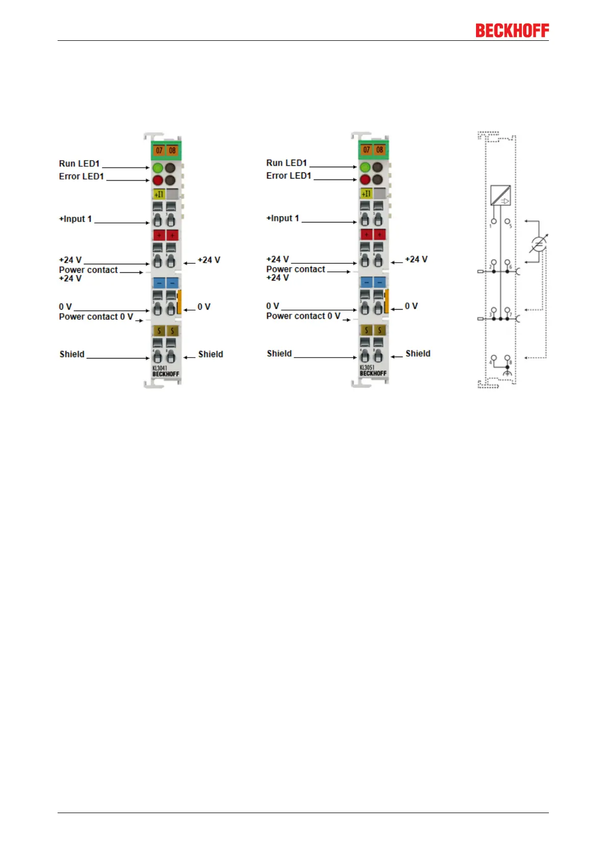
Fig.1: KL3041, KL3051
The job of the KL3041 and KL3051 analog input terminals is to supply power to measuring transducers
located in the field, and to transmit analog measurement signals with electrical isolation to the automation
device.
The KL3041 terminal processes signals in the range from 0mA to 20mA.
The KL3051 terminal processes signals in the range from 4mA to 20mA.
The voltage for the sensors is supplied to the terminals via the power contacts. The power contacts can
optionally be supplied with operating voltage in the standard way or via a power feed terminal (KL9xxx) with
electrical isolation. The input electronics is independent of the supply voltage of the power contacts. The 0 V
rail is the reference potential for the inputs. The Run LEDs indicate the exchange of data with the Bus
Coupler, while the Error LEDs indicate overload and wire breakage.
 Loading...