HEAD BOARD
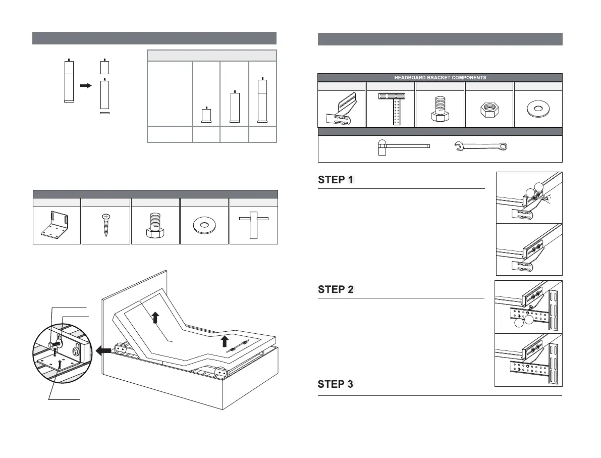
Lift the head and foot end of the bed by remote control. Install four stabilizer brackets as
shown. Use a phillips screwdriver and socket wrench to tighten the screws and bolts.
Headboard Bracket Installation Guide (Optional)
Headboard brackets are optional and not included. A 1/2” (13 mm)
socket and 1/2” (13 mm) wrench are required to complete the installation.
1
2
2
1
a) Align the slot hole of the headboard bracket to the sleeve into
which the leg threads. DO NOT OVERTIGHTEN. Too much force
may damage the thread.
b) The headboard bracket has 2 adjustable slots to accommodate
any frame type. Use the bolts and washers to secure the bracket.
Make sure the bolts are tight.
a) To put the T-Bracket and Headboard Bracket together, you will
need (2) M8×16 bolts and (2) nuts. Slip the bolts through the holes
from T-Bracket to Headboard Bracket with the head of bolt facing
outward. Use the 1/2” (13 mm) socket and 1/2” (13mm) wrench to
tighten the bolts.
You may now connect your headboard to the attachment plates using the remaining short bolts
and nuts to secure it to the brackets. The heads of the bolts will face outward. Use a 1/2” (13mm)
socket and 1/2” (13mm) wrench to tighten the bolts.
(2) Headboard Brackets
(2) T-Brackets (8) M8*16 (4) Nuts (4) Washers
Stabilizer Brackets are optional and not included. They can fix the
bed onto the slat base. A phillips screwdriver and socket wrench
are
required to complete the installation.
(4) Stabilizer Brackets (1) Socket Wrench(8) Screws ST4.2×16 (8) Bolts M8*16 (8) Washers
STABILIZER BRACKETS COMPONENTS
OPTIONAL EQUIPMENT/PART (NOT INCLUDED)
Socket and Wrench 1/2'' (13mm)
Legs Installation Guide
Support leg may be needed on some slat/platform bed frames, refer
to the leg configuration table for height adjustment.
* Make sure the adjustable legs are properly tight, and the plastic caps have been placed at
the bottom of the legs. Incorrect installation might cause the part to fail or damage the floor.
Leg
Configuration
Leg Height
Leg Configuration Table
4 " 7⁵⁄8 " 11³⁄8 "
×6
Included in
Accessories Box
(See Page 2
for details)
Screws
ST4.2×16
M8*16 Bolts
Washers
- 13 -
 Loading...