921 VOLTAGE CONTROLLED
OSCILLATOR Controls
(4)
(5)
(6)
(3)
(8)
(7)
(10)
(11)
(13)
(12)
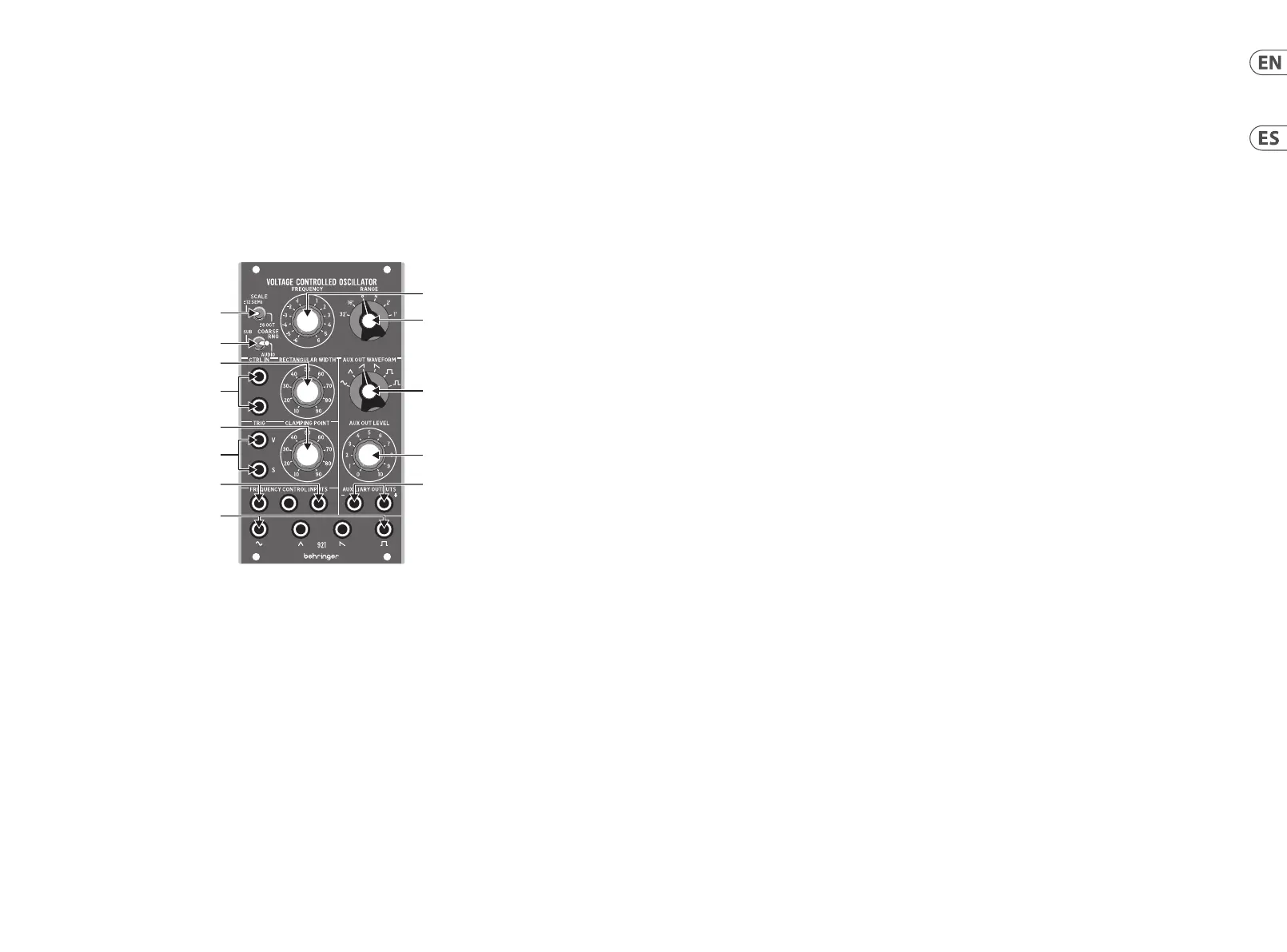
(EN) Controls
(1) FREQUENCY – Use this knob to set the oscillator
frequency. The frequency settings for this knob are
controlled by the COARSE RNG and SCALE toggle switches,
as well as the RANGE rotary switch.
(2) RANGE – This knob sets the general frequency range
of the oscillator in one-octave steps, which can then be
adjusted up or down with the FREQUENCY knob.
(3) SCALE – This switch controls whether the frequency knob
scale is ±6 octaves or ±12 semitones, which gives ner
frequency control.
(4) COARSE RNG – This switch controls whether the oscillator
frequency functions in the audio range or in a lower
frequency range that extends below the audio threshold.
(5) RECTANGULAR WIDTH – Use this knob to set a default
width for the rectangular waveform. The width can then
be further controlled and varied by control voltages routed
in via the CNTRL IN jacks.
(6) CNTRL IN – These summed jacks allow control voltage
and modulation signals for the rectangular waveform to
be routed in via cables with 3.5 mm TS connectors.
(7) CLAMPING POINT – Use this knob to set the point at
which the oscillator waveform resets.
(8) TRIG (V/S) – These jacks allow control signals for the
clamping point to be routed in via cables with 3.5 mm TS
connectors. The clamping point can be triggered with a
V-Trig (voltage trigger) signal via the V jack, or a S-Trig
(switch trigger) signal via the S jack.
(9) AUX OUT WAVEFORM – Use this knob to select a
waveform for the auxiliary output signal, including sine,
triangular, sawtooth, inverted sawtooth, square and
inverted square waveforms.
(10) AUX OUT LEVEL – Use this knob to adjust the output level
for the AUXILIARY OUTPUT jacks.
(11) AUXILIARY OUTPUTS – Use these jacks to route an
auxiliary waveform signal out of the module via cables
with 3.5 mm TS connectors.
(12) FREQUENCY CONTROL INPUTS – Use these summed
jacks to route control voltage and modulation signals into
the oscillator via cables with 3.5 mm connectors.
(13) WAVEFORM OUTPUTS – Use these jacks to route
oscillator signals out of the module via cables with 3.5
mm jacks. Four waveforms are available: sine, triangular,
sawtooth and rectangular.
(ES) Controles
(1) FREQUENCY - Utilice este mando para congurar la
frecuencia del oscilador. Los ajustes de frecuencia para
esta perilla se controlan mediante los interruptores de
palanca COARSE RNG y SCALE, así como el interruptor
giratorio RANGE.
(2) RANGE - Esta perilla establece el rango de frecuencia
general del oscilador en pasos de una octava, que luego
se pueden ajustar hacia arriba o hacia abajo con la
perillaFREQUENCY.
(3) SCALE - Este interruptor controla si la escala de la perilla
de frecuencia es ± 6 octavas o ± 12 semitonos, lo que
proporciona un control de frecuencia más no.
(4) COARSE RNG - Este interruptor controla si la frecuencia
del oscilador funciona en el rango de audio o en un rango
de frecuencia más bajo que se extiende por debajo del
umbral de audio.
(5) RECTANGULAR WIDTH - Utilice esta perilla para
establecer un ancho predeterminado para la forma de
onda rectangular. Luego, el ancho puede controlarse y
variarse aún más mediante voltajes de control enrutados a
través de las tomas CNTRL IN.
(6) CNTRL IN - Estos conectores sumados permiten enrutar
la tensión de control y las señales de modulación para
la forma de onda rectangular a través de cables con
conectores TS de 3,5 mm.
(7) CLAMPING POINT - Utilice este mando para establecer
el punto en el que se restablece la forma de onda
deloscilador.
(8) TRIG (V / S) - Estas tomas permiten enrutar las señales
de control para el punto de sujeción a través de cables
con conectores TS de 3,5 mm. El punto de sujeción se
puede activar con una señal V-Trig (disparador de voltaje)
a través del conector V, o una señal S-Trig (disparador de
interruptor) a través del conector S.
(9) AUX OUT WAVEFORM - Utilice esta perilla para
seleccionar una forma de onda para la señal de salida
auxiliar, incluidas las formas de onda sinusoidal,
triangular, de diente de sierra, de diente de sierra
invertido, cuadrada y cuadrada invertida.
(10) AUX OUT LEVEL - Utilice esta perilla para ajustar el nivel
de salida de las tomas AUXILIARY OUTPUT.
(11) AUXILIARY OUTPUTS - Utilice estas tomas para enrutar
una señal de forma de onda auxiliar fuera del módulo a
través de cables con conectores TS de 3,5 mm.
(12) FREQUENCY CONTROL INPUTS - Utilice estos conectores
sumados para enrutar el voltaje de control y las señales de
modulación al oscilador a través de cables con conectores
de 3,5 mm.
(13) WAVEFORM OUTPUTS - Utilice estas tomas para enrutar
las señales del oscilador fuera del módulo a través de
cables con tomas de 3,5 mm. Hay cuatro formas de onda
disponibles: sinusoidal, triangular, de diente de sierra
yrectangular.
4 5Quick Start Guide921 VOLTAGE CONTROLLED OSCILLATOR
 Loading...