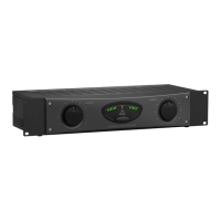
12 13REFERENCE AMPLIFIER A500 Quick Start Guide
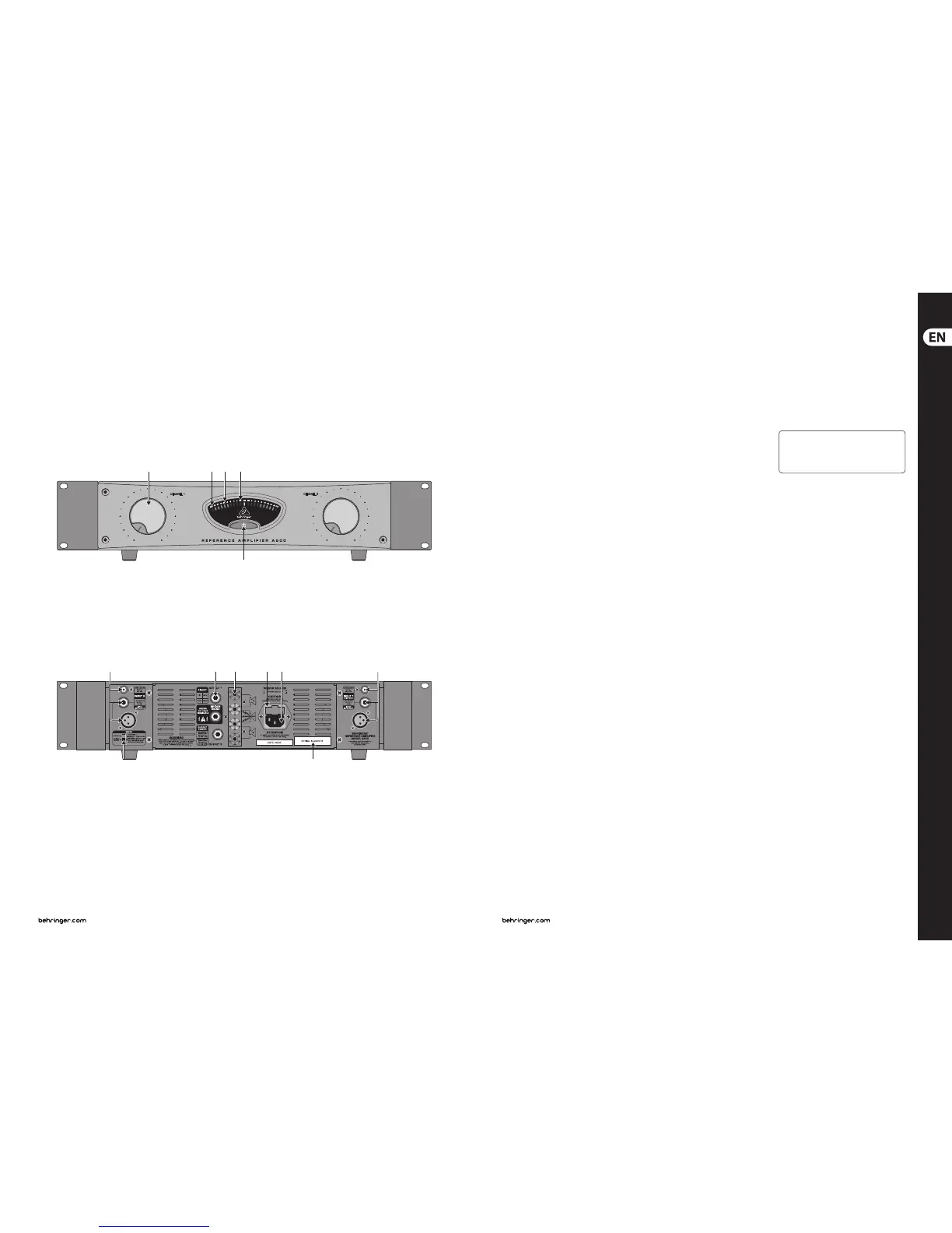
REFERENCE AMPLIFIER A500 Controls
(2) (3) (4) (5)
(1)
(9) (10)
(13)(8)
(11) (12) (6)(7)
(EN) Controls
(1) The POWER switch is used to power up the
A500. The POWER switch should always be
in its “O” position when you connect the
unit to the mains.
POWER LED lights up as soon as you power
up the A500.
(2) Each channel features a volume control.
Useit to adjust gain on your A500. Both
volume controls should be turned all the
way to the left whenever you power the unit
up or down. If an active signal is present on
the input, turningthe volume down will
protect your speakers and your ears from
unwanted “pops” or transients.
(3) The PROT LED lights up whenever the
protective circuitry mutes the speaker
output. Please turn your A500 o
immediately whenever this LED is lit.
(4) The high-precision power indicator gives out
current signal strength.
(5) The CLIP LED lights up when the signal
is distorted. Should distortion occur,
reducethe input level, so that the CLIP LED
no longer lights up.
(6) CHANNEL INPUT 1 (MONO). Connectthe
signal source whose output needs to
beamplied.
(7) CHANNEL INPUT 2. These are the inputs for
channel 2.
(8) The STEREO/BRIDGED MONO switch is used
to toggle between the two operating modes
of your A500.
◊ Please power the A500 down
using the POWER switch each time
you change the operating mode.
Similarly,onlyconnect/disconnect
speaker connectors if the A500 has rst
been powered o!
(9) OUTPUT 1, OUTPUT 2 and BRIDGED
MONO: These are the speaker connectors
of your A500 laid out as ¼" TS mono
connectors. When in mono-bridged mode,
only use the BRIDGED MONO output.
(10) In addition to XLR or ¼" TRS connectors,
youcan also use binding posts for
connecting speaker cables. When in mono-
bridged mode, make sure to connect your
cables to both middle connectors–as shown
on the unititself.
(11) FUSE SWITCH/VOLTAGE SELECTION.
(12) The mains connection is made via a standard
IEC RECEPTACLE. A matching cable
isenclosed.
(13) SERIAL NUMBER.
For more details on the full functionality
of this product, see the product page
on behringer.com and download the
full manual.