Controls
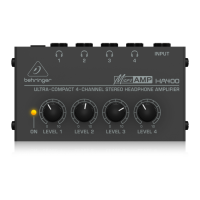
1. LEVEL control: To adjust the input level of a signal, turn this control toward 0 (minimum level) or, alternatively 6
(maximum level).
2. BALANCE control: To adjust the stereo image of a signal, turn this control toward L (left) or, alternatively R
(right).
3. A + B meter: To monitor the combined level of both signals (A and B), use this meter. An LED glows next to the
value that identifies the combined level (-24 dB to 0 dB). If the signal is too strong, the CLIP LED glows. Most of
the time, the optimal level is 0 dB (a full signal).
4. (headphone) connector: To connect a headphone, use this stereo, ¼” TRS connector.
5. INPUT button: To select an Input Channel, push this button.
6. PHONES LEVEL control: To adjust the level of a headphone signal, turn this control toward 0 (minimum
volume) or, alternatively 6 (maximum volume).
7. CH meter: To monitor the level of a headphone signal, use this meter. An LED glows next tothe value that
identifies the headphone volume (-24 dB to 0 dB). If the signal is too strong, the CLIP LED glows. Most of the
time, the optimal volume is 0 dB (a full signal).
8. (power) button: To turn the AMP800 on and off, push this button.
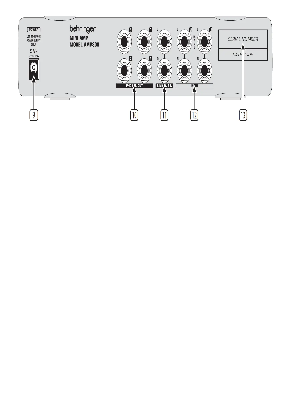
9. POWER connector.
10. PHONES OUT connectors: For each Headphone Channel (1, 2, 3, and 4), the rear panel includes an additional
headphone connector, which is a stereo, ¼” TRS connector.
11. LINK OUT A connectors: If you need more than the 4 Headphone Channels that a single AMP800 provides,
connect these balanced, ¼” TRS connectors (Left and Right) to the inputs of another AMP800. The LINK OUT
A connectors send only the signal of Input Channel A, without any LEVEL or BALANCE settings.
12. INPUT connectors: For each Input Channel (A and B), the rear panel includes 2 balanced, ¼” TRS connectors
(Left and Right).
13. SERIAL NUMBER.
Specifications
Input
Type ¼” TRS connector, balanced
Impedance
approx. 20 kΩ, balanced /
approx. 10 kΩ, unbalanced
CMRR 40 dB typ. @ 1 kHz
Phones Out