16 SYSTEM 55 Quick Start Guide 17
Control settings are very important for this patch.
Regeneration on the 904A LPF must be set to 9 or 10 to force the lter to self oscillate
The 921A should have Octave selected and the frequency control set to -6
The 921B VCOs should be set to ‘Lo’ – these oscillators provide the sweep to the lters
The 921 LFO should be set to ‘Sub’ – this is the main modulation for the self oscillating lter, and manual alteration of the Frequency control helps to produce the
classic sound.
The pink noise feeding the 904B HPF produces a swept wind eect, that can be altered with the Fixed Control Voltage
Altering the Fixed Control Voltage of the 904A LPF also produces interesting eects
The CP3A-M balances the two signals, as an alternative feed the outputs of the two lters direct to two mixer or amplier channels. Both sounds benet
from a lot of echo!
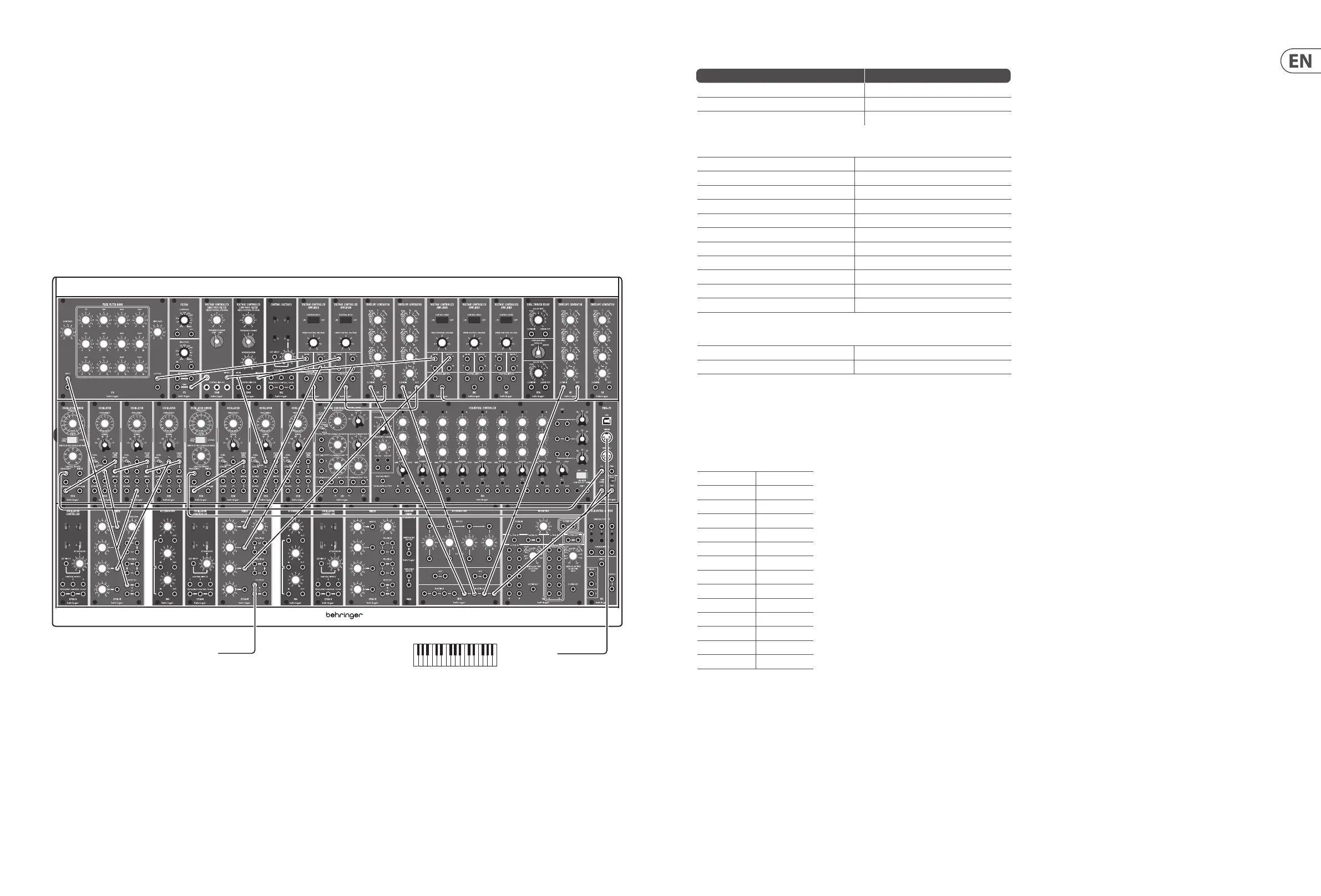
Mellow Organ
A mellow sound using the 914 FFB that can easily be changed to something more aggressive by changing the settings.
MIDI OutTo mixer/amplier/DAW
Voltage Control (pitch)
Source Destination
External MIDI Keyboard – MIDI Out CM1A MIDI Interface MIDI In
CM1A CV Output via Multiple 921A Frequency Input x 2
921A Oscillator Controller Frequency Output x 2 921B Oscillator Frequency Link (in series)
Audio
1st 921B Triangle Output CP3A-M Input 1
2nd 921B Square Output CP3A-M Input 2
3rd 921B Sine Output CP3A-M Input 3
CP3A-M Output 914 Input
4th 921B Sine Output 904A Signal Input
923 Pink Noise Output 904B Signal Input
914 Signal Output 1st 902 Signal Input
904A Signal Output 2nd 902 Signal Input
904B Signal Output 3rd 902 Signal Input
3 x 902 Signal Output CP3A-M Mixer Inputs 1-3
CPO3A-M Mixer Output Your Mixer/Amplier/DAW
Voltage Control (Amplitude)
CM1A s-trigger Output 3 x 911 via Multiple
3 x 911 Output 3 x 902 Control Input
There are three components to this sound. The main organ sound is generated by the rst three 921Bs and the 914 FFB. The second comes from the fourth 921B and
the 904A LPF and the third from the 923 Pink Noise and the 904B HPF. Certain settings are important, but variations can easily be achieved.
The main organ sound mixes Triangle, Square and Sine waves from three 921Bs. The width control on the 921A would normally be at 50%, giving a pure Square Wave,
but can be made more ‘nasal’ by increasing this or more mellow by decreasing. The basic sound has all waveforms at equal volume, but new sounds can be created by
altering the balance.
The settings of the 914 are also important. For the basic sound they should be:
Low Pass 0
125 4
175 4
250 0
350 5
500 3.5
700 0
1000 0
1400 1
2000 0
2800 0
4000 0
5600 0
High Pass 0
Experiment with dierent values – adding in higher frequencies makes the sound more aggressive, for example.
The 911 EG should have minimum T1 (attack) and T3 (release); long T2 (decay) and E sus(tain)
The second element is a tuned percussive sound on key press. This is derived from the sine wave of the fourth 921B and the 904A LPF. The envelope settings are
minimum T1 (attack) and T3 (release) and E sus(tain); 500ms T2 (decay)
The third element is the untuned percussive sound on key press. This is derived from the pink noise of the 923 and the 904B HPF. Envelope settings are minimum T1
(attack) and T3 (release) and E sus(tain); 5ms T2 (decay) . This element should be kept down in the mix