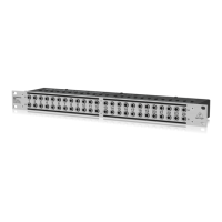
12 13ULTRAPATCH PRO PX300 0 Quick Start Guide
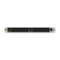
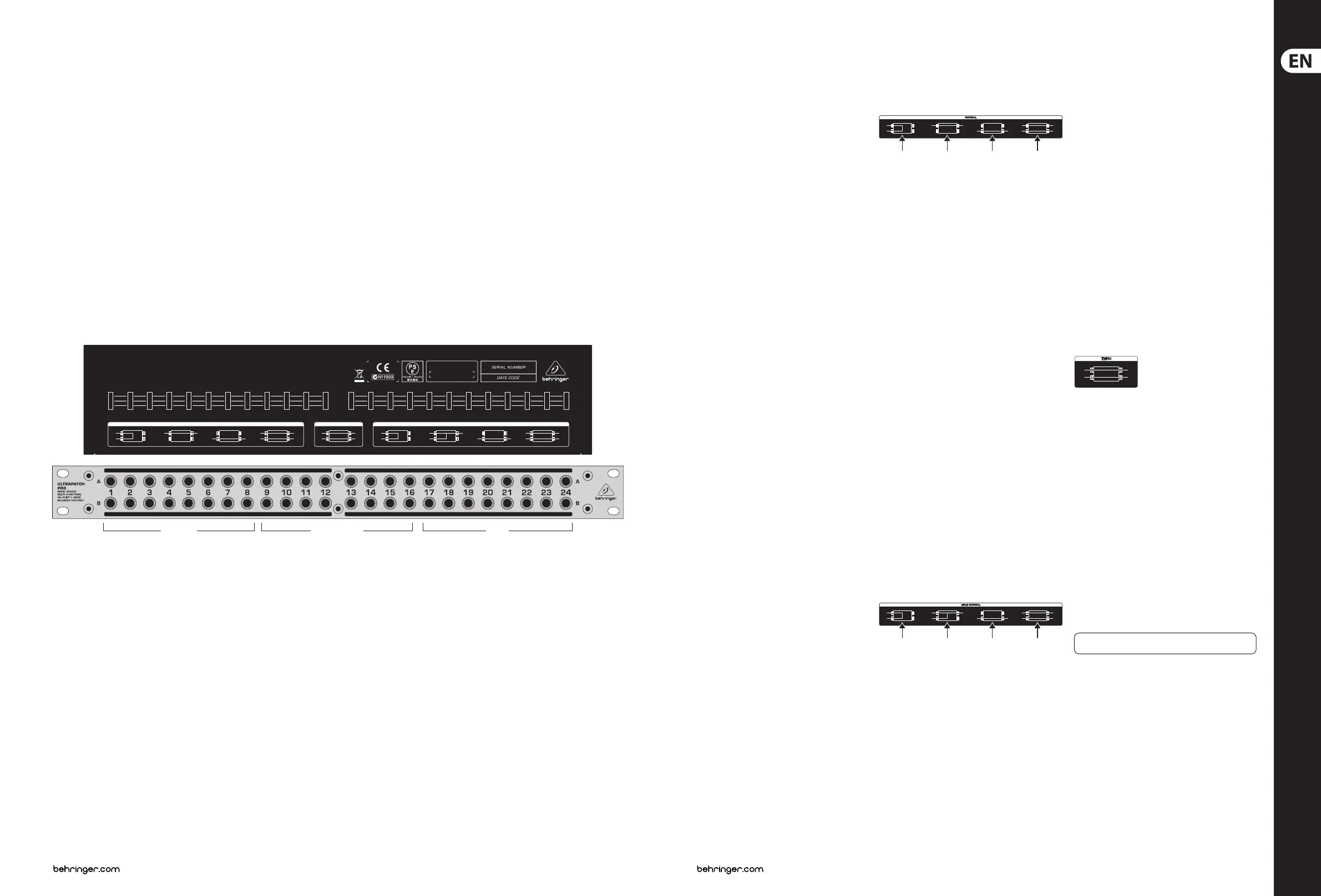
ULTRAPATCH PRO PX3000 Controls
REAR FRONT
ULTRAPATCH PRO
MULTI
–
FUNCTIONAL 48
–
POINT 3
–
MODE BALANCED PATCHBAY MODEL PX3000
REAR FRONT REAR FRONT REAR FRONT REAR FRONT REAR FRONT REAR FRONT REAR FRONTREAR FRONT
HALF NORMAL
THRU
NORMAL
CONCEIVED AND DESIGNED
BY BEHRINGER GERMANY.
MADE IN CHINA
型 号: PX3000 平衡式接线槽
NORMAL THRU HALF NORMAL
A
B
A
B
A
B
A
B
A
B
A
B
A
B
A
B
A
B
制造商
:
BEHRINGER Holdings (P te) Ltd
中国制造
NORMAL HALF NORMAL THRU
(EN) Controls
NORMAL MODE
In NORMAL mode the rear A & B jacks of the channel are
connected together (pos. (1)). The connection between
the rear jacks is disabled when you insert a cable into jack
A or B on the front panel (pos. (2) and (3)).
In the example above, top-row channels 1 to 4 are from
the outputs of a keyboard and a MIDI sound module.
Theyare connected, in this example conguration,
toinput channels 1 to 4 on the mixer.
Channels 5 and 6 are from the subgroup outputs of a
mixer and are connected, in this example conguration,
to the inputs of a computer audio card. Audio sequencer
software records the music signals directly onto the
hard disk of the computer. Channels 7 and 8 connect the
soundcard outputs to the 2-track inputs of the mixer.
Since the rear-panel jacks are connected together in
the Normal mode (pos. (1)), the subgroup signals can
be recorded directly onto the PC and played back via
the 2-track input of the mixer (playback/monitoring),
without a single patch cable having to be plugged in!
Inthis way, you can build up a basic conguration for your
studio, which can be easily modied by simply patching
signals via the front-panel jacks (pos. (2)) or by feeding
in external signals via patch cables (pos. (3)). You could,
forexample, connect the keyboard signal to channels 3
and 4 by patching 1A to 3B, and 2A to 4B. So, before wiring
your studio, it is advisable to identify the connections that
will be used most frequently and set them up, as your
basic conguration, one above the other on the patchbay.
Then you will have a clear overview of all connections and
still be exible.
HALF-NORMAL MODE
In HALF NORMAL mode, the rear A & B jacks of the channel
are connected together (pos. (1)). Unlike NORMAL
mode, the connection between the rear-panel jacks
is not disabled when a ¼" plug is inserted into jack A
on the front panel (pos. (2)). This allows you to take
the signal from a mixers channel strip in parallel—
withoutinterrupting the signal path on the channel
strip. Like NORMAL mode, the connection between the
rear-panel jacks is disabled when a ¼" plug is inserted into
jack B on the front panel (pos. (3)). When ¼" plugs are
inserted into both jacks A & B on the front panel, the front
jacks will be connected separately to the corresponding
rear jacks (pos. (4)). This is called an “input break” and
is used mainly to insert an eect or processor into the
signalpath.
In the example above, top-row channels 9 to 14 are the
sends (tip contact of insert points) from mixer channels 1
to 4 plus the main left & right sends. They are connected,
in this example conguration, to their respective returns
(ring contacts of insert points) of the mixer.
Outputs from the mixer sends can be taken from jack A
without disabling the connection to the returns (pos. (2)).
The mixer returns can be used as external line inputs,
bypatching cables to jack B (pos. (3)). External eects or
processors can be inserted into the send-return loop by
connecting their inputs & outputs to jacks A & B (pos. (4)).
The main left & right outputs of the mixer are connected,
in this example conguration, to a mini-disc recorder.
However, they can also be connected in parallel to
another recorder (pos. (2)). The mini-disc recorder can
record other sources when they are connected to jack B of
channels 15 and 16 (pos. (4))
THRU MODE
This mode is for sound modules or playback devices
(e.g. CD players) that only have output signals. You can
save space by routing the left and right outputs to one
channel (jacks A & B) of the patchbay. A more typical
setup is to connect the left and right outputs to adjacent
channels (jacks A & A) and then connect another device to
jacks B & B of the same channels. This conguration also
allows you to position the inputs and outputs of eects
devices, compressors, equalizers, etc. directly above
each other.
In the example conguration above, the outputs ofthe
playback devices (CD and mini-disc) plus the four
individual outputs of a sampler are connected to channels
17 to 20, while channels 21 to 24 are used for the inputs
& outputs of a compressor and an EQ, which are usually
connected to the inserts of a mixer.
REAR FRONT REAR FRONT REAR FRONT RE AR FRONT
A
B
A
B
A
B
A
B
REAR FRONT REA R FRONT REAR FRONT REAR FRONT
A
B
A
B
A
B
A
B
REAR FRONT
A
B
Check Out behringer.com for Full Manual
 Loading...