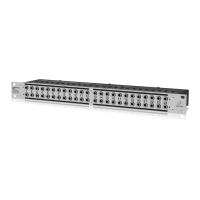
The BEHRINGER ULTRAPATCH PX1000 is a multi-functional, balanced 48-point patchbay designed for studio and stage applications. Its primary function is to centralize and streamline the audio signal routing of various components within a studio or stage setup, making cabling more organized and efficient for professional work. Even smaller studio configurations can benefit from less complex patchbay arrangements.
Function Description:
The PX1000 features two rows of 24 1/4" TRS phone jacks on a single 19" rack panel. Each group of four phone jacks forms one module, and the patchbay's configuration can be changed by manually aligning these modules. This allows for five different operational modes, providing flexibility in signal routing. To change modes, users simply loosen the two lower front screws to remove the front panel and adjust the modules.
Operational Modes:
- Mode 1 (Normalled): In this mode, when all jacks of a module are inserted, audio signals A and B are routed separately from front to rear. This is useful for connecting mixer outputs to compressor inputs or compressor outputs to tape inputs, for example.
- Mode 2 (Input Break): Here, the contacts of jacks A & B on the front are interconnected. Inserting a plug into the upper rear jack (A) does not interrupt the signal routed through the front path. However, using the lower rear jack (B) splits the front panel route, connecting the two upper and two lower jacks. This configuration is primarily used for insert applications.
- Mode 3 (Parallel Rear): In this mode, the contacts of jacks A & B on the rear are interconnected. Inserting a plug into the upper front jack (A) does not interrupt the signal routed through the rear path, and the audio source of front A is paralleled to the rear jacks (A & B). This allows, for instance, two power amplifiers to share one audio source.
- Mode 4 (Parallel Front): In this configuration, the contacts of jacks A & B on the front are interconnected. The upper front jack (A) receives an incoming signal, and the lower front jack (B) sends the outgoing signal. This mode is suitable for recording purposes or connecting to additional equipment.
- Mode 5 (Fixed Installation): Similar to Mode 4, the contacts of jacks A & B on the rear are interconnected. This mode is typically used for equipment in a fixed installation, such as connecting mixer outputs to recorder inputs in recording studios. The permanent rear connections allow for easy interception, diversion, or replacement of the signal at the front of the patchbay by inserting a plug into either front jack (A or B).
Important Technical Specifications:
- Height: 1 3/4" (44.5 mm)
- Width: 19" (482.6 mm)
- Depth: 2 3/4" (69.3 mm)
- Weight: approx. 1.3 kg (2 7/8 lbs)
- Connectors: 1/4" TRS balanced
Usage Features:
The PX1000 is designed for ease of use, allowing users to quickly reconfigure signal paths by manually adjusting modules. The inclusion of white labels above the upper jacks and below the lower jacks facilitates clear identification of patch points. Users are advised to use non-permanent markers for labeling, as signal routing may change over time.
Maintenance Features and Cautions:
- Grounding and Looming: Proper loom wiring is crucial to avoid ground loops, which can cause hum and electromagnetic radiation. All screens should ideally be commoned at the patchbay, with mains-earthed equipment having screens cut at the equipment end. Patch leads should be as short as possible with screens connected at both ends.
- Digital Signals: Avoid routing digital signals near the patchbay, as pulse signals can cause heavy interference in analog signals and change the impedance of the digital cable route. For digital signal-related functions, the BEHRINGER ULTRAMATCH PRO SRC2496 is recommended.
- Microphone Inputs: Microphone inputs operate at much lower levels than line levels and should never be routed via a patchbay. Patching in a field with +48 V DC (phantom power) must be avoided at all costs. Microphones should be plugged directly into the mixing console or via special XLR type wall boxes connected to the console's mic inputs using high-quality balanced multicore cables.
- Organization: Patchbays should be placed one below the other to prevent patch cords from hanging carelessly.
- Warranty: The product comes with a one-year warranty on mechanical and electronic components, extendable by returning the warranty card or registering online within 14 days of purchase. The warranty covers defects in material and workmanship but excludes issues caused by improper handling, neglect, normal wear and tear, unauthorized repairs, or force majeure. Warranty service requires a return authorization number and proof of purchase.
The BEHRINGER ULTRAPATCH PX1000 is a robust and flexible solution for managing complex audio signal flows in professional environments, emphasizing organization, signal integrity, and user-friendly configuration.