16
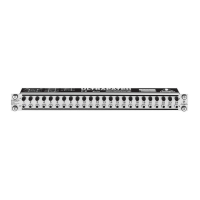
4.2 Rear panel control elements
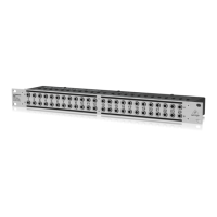
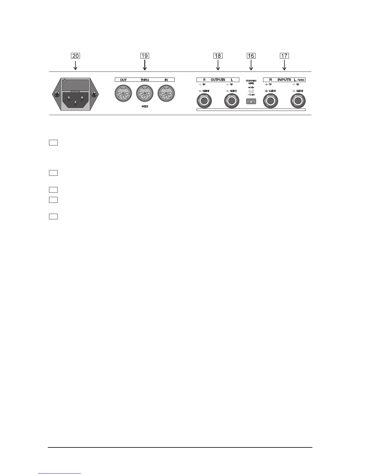
Fig. 4.4: Connectors and control elements of the rear panel
16
Use the OPERATING LEVEL switch to adapt the VIRTUALIZER to different operating levels. You can
select a -10 dBV semi-pro level used for home recording and a +4 dBu level used in professional studios.
The level indicators on the front panel are automatically adapted to read the selected nominal level, i.e.
an optimum operating range of the meters is always guaranteed.
17
The VIRTUALIZER was designed for operation with unbalanced mono phone jacks (6.3 mm). Each
audio channel (left/right) has a phone jack INPUT for incoming signals.
18
The two OUTPUTS of the VIRTUALIZER also have one unbalanced phone jack for each audio channel.
19
The VIRTUALIZER features extensive MIDI implementation. In addition to the standard MIDI IN and MIDI
OUT connectors, you can loop through MIDI signals by using the MIDI THRU jack.
20
Use the enclosed power cord and ICE mains connector to connect the VIRTUALIZER to the mains
power supply (See also chap. 3.1).
4. CONTROL ELEMENTS