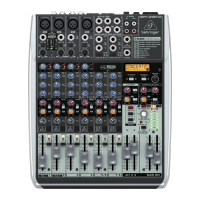
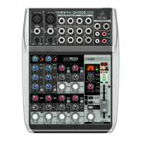
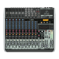
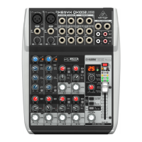
marked “L”(left) is used, the channel operates in mono. The stereo channels are designed to handle typical line level signals.
Both inputs will also accept unbalanced jacks.
11. FX – The FX sends of the stereo channels function similar to those of the mono channels. However, since the FX send
buses are both mono, a mono sum is first taken from the stereo input before it is sent to the FX bus.
12. BAL – The BAL(ANCE) control determines the levels of left and right input signals relative to each other before both signals
are then routed to the main stereo mix bus. If a channel is operated in mono via the left line input, this control has the same
function as the PAN control used in the mono channels.
13. +4/-10 – The stereo inputs of the
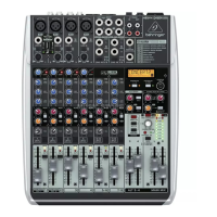
XENYX QX1002USB and QX1202USB have an input sensitivity switch which selects between +4 dBu and -10 dBV. At -10
dBV (home-recording level), the input is more sensitive (requires less level to drive it) than at +4 dBu (studio level).
14. FX TO MAIN – The FX TO MAIN control feeds the effects signal into the main mix. If the control is turned all the way
counterclockwise, no effects signal is present in the sum signal of the mixing console.
15. FX SEND – The FX SEND connector outputs the signal you picked up from the individual channels using the FX controls.
You can connect this to the input of an external effects device in order to process the FX bus’ master signal. Once an effects
mix is created, the processed signal can then be routed from the effects device outputs back into a stereo input.
16. PHONES/CONTROL ROOM – The stereo PHONES jack (at the top of the connector panel) is where you connect
headphones. The unbalanced CTRL ROOM OUT jacks carry the summed effects and main mix signals, as well as soloed
channel signals. The PHONES/CONTROL ROOM control adjusts the level of both headphones and main monitor outputs.
17. MAIN MIX – The MAIN OUT connectors are balanced mono jacks. The main mix signal appears here at a level of 0 dBu.
The MAIN MIX fader adjusts the volume of these outputs.
18. CD/TAPE INPUT – The CD/TAPE INPUTs are used to bring an external signal source (e.g. CD player, tape deck, etc.) into
the console. They can also be used as a standard stereo line input, so the output of a second XENYX or BEHRINGER
ULTRALINK PRO MX882 can be connected.
19. CD/TAPE OUTPUT – These connectors are wired in parallel with the MAIN OUT and carry the main mix signal
(unbalanced). Connect the CD/TAPE OUTPUT to the inputs of your recording device. The output level is adjusted via the
high-precision MAIN MIX fader.
20. USB/2-TR TO PHONES/CTRL RM – button routes USB/2-Track playback to PHONES/CTRL ROOM.
21. USB/2-TR TO MAIN MIX button routes USB/2-Track playback to MAIN MIX and mutes the 2-TR OUT/USB recording signal.
22. FX TO CTRL ROOM – If you want to monitor only the FX send signal in your headphones or monitor speaker(s), press the
FX TO CTRL switch. This mutes the main mix signal while routing the FX SEND output to the monitor(s).
23. +48 V – The +48 V LED lights up when phantom power is on. The PHANTOM switch activates the phantom power supply
on the XLR connectors of all mono channels.
24. POWER – The POWER LED indicates that the console is powered on.
25. LEVEL INDICATOR – The high-precision 4-segment display accurately displays the relevant signal level.
26. SIGNAL and CLIP LED – The SIGNAL LED on the effects module shows the presence of a signal whose level is high
enough. This LED should always be on. However, make sure that the CLIP LED lights up only sporadically. If it is lit
constantly, you are overdriving the effects processor, which leads to unpleasant distortion. If this occurs, turn the FX controls
down somewhat.
27. PROGRAM – The PROGRAM control has two functions: by turning the PROGRAM control, you dial the number of an effect.
The number of the preset you just dialed up blinks in the display. To confirm your selection, press the PROGRAM control;
the blinking stops.
28. COMP – This knob adjusts the amount of compression effect on the channel.
29. PHANTOM – Press this button to send +48 V of phantom power to the XLR inputs for use with condenser microphones.
30. USB CONNECTOR – Connect your mixer to a computer using a standard USB cable.
31. AC POWER IN – Connect the included power cable here.
The mixer cannot be bus-powered via USB. Always use the included power adapter to supply power to the mixer.
Getting started
To correctly set the gains of the channels, first set the LEVEL controls of the input channels to their center positions (0 dB). Then
use the GAIN controls to increase the input amplification until signal peaks show 0 dB on the level meter.
When recording to digital recorders, the recorder’s peak meter should not go into overload. While analog recorders can be
overloaded to some extent, creating only a certain amount of distortion (which is common and often desirable), digital recorders
distort quickly when overloaded. In addition, digital distortion is not only undesirable, but also renders your recording completely
useless. The peak meters of your XENYX display the level virtually independent of frequency. A recording level of 0 dB is
recommended for all signal types.
Presets List
Reverb
 Loading...

