6. HMI Panel Drawings
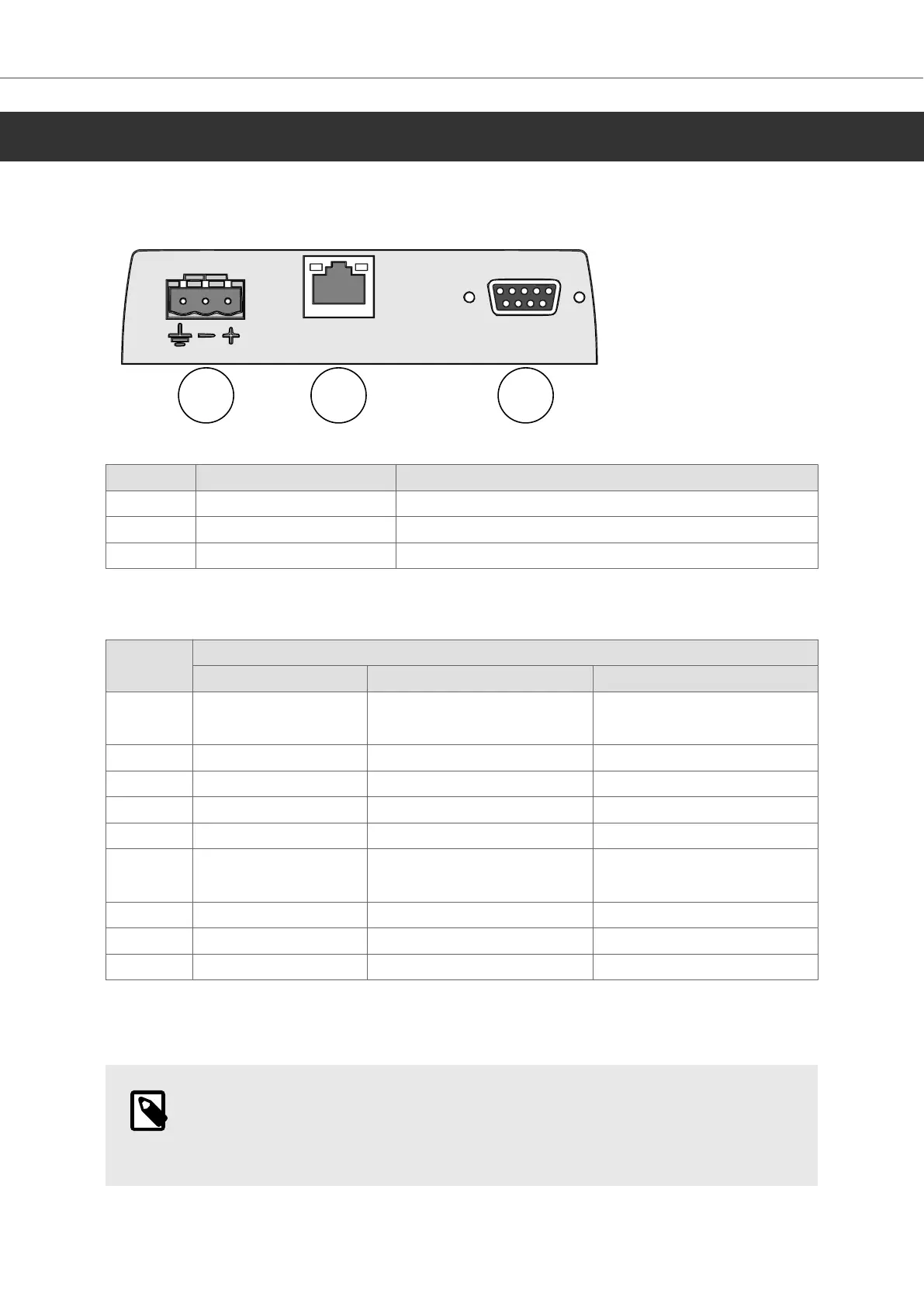
6.1. Connectors
Pos Connector Description
1 Power supply +24 V DC (18–32 V DC)
2 LAN A 1×10/100 Base-T (shielded RJ45)
3 COM Serial communication port
6.1.1. Communication Ports
Pin D-sub-9, female
COM 1 COM 2 COM 3
1 RS-422 Tx+
RS-485 Tx+/Rx+
2 RS-232 RxD
3 RS-232 TxD
4 RS-422 Rx+ RS-485 Tx+/Rx+
5 GND GND GND
6 RS-422 Tx-
RS-485 Tx-/Rx-
7 RS-232 RTS
8 RS-232 CTS
9 RS-422 RX- RS-485 Tx-/Rx-
The connector supports up to three independent serial communication channels and can be
configured for RS-232 and RS-422 or 2×RS-485.
NOTE
In order to utilize two communication ports, the Y-split cable CAB109 can be used.
To use RS-232 and RS-422, use CAB 109.
HMI Panel Drawings
2024-01 18 Beijer Electronics, MAEN364