In stallation
5.
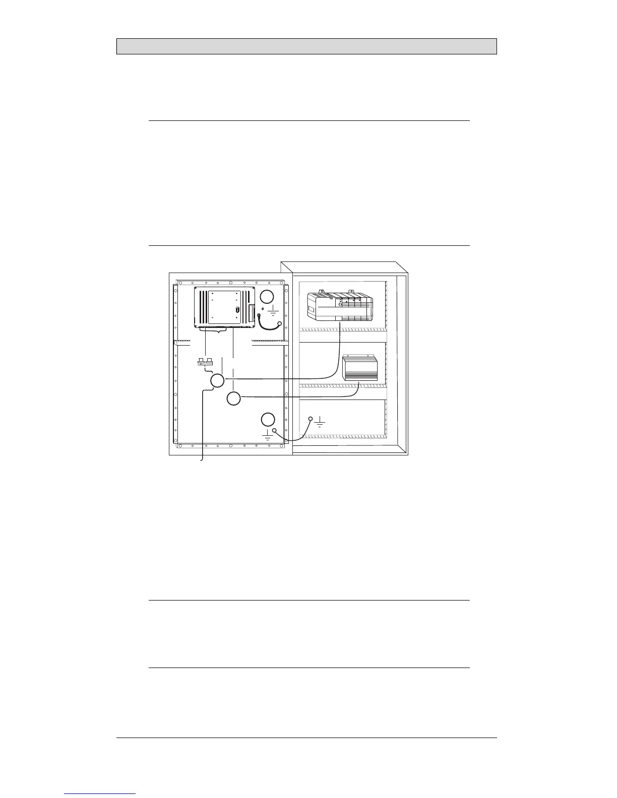
Connect the cables in the specified order, acc ording to the drawing and steps
below.
Caution:
• Theoperatorpanelmustbebroughttoambienttemperaturebeforeitisstarted
up. Ifcondensationforms,ensurethattheoperatorpanelisdrybeforeconnecting
ittothepoweroutlet.
• Ensurethattheoperatorpanelandthecontrollersystemhavethesameelectrical
grounding(referencevoltagelevel),otherwiseerrorsincommunicationmay
occur.
• Ensurethatthevoltageandpolarityofthepowersourceiscorrect.
• Separatehighvoltagecablesfromsignalandsupplycables.
• Shieldedcommunicationcablesarerecommended.
24V DC
RS232/
RS422/
RS485
24V DC
A
D
Controller
Power
B
Ethernet
C
– Connect cable A.
– Connect cable B, using an M5 sc
rew and a grounding conductor (as short
as possible), that is size
d c orrectly according to local electrical codes.
– Connect cable C.
– Connect cable D. The rec
ommended cross-section of the cable is
1.5 mm
2
..
6.
Carefully remove the pro
tective film over the operator panel display, take care
to avoid static electri
city that could damage the panel.
Note:
Whenconnectingtheoperatorpaneltothepoweroutletforthefirsttime,make
surenottointerruptpowerforaminimumof48hoursinordertochargethebattery
completely. Afterthat,thebatterymayb echargedpartlyduringashorterp eriodof
time.
BeijerElectronics, MAEN181B
8