ITALIANO ENGLISH MICROTEC 810
18
COD. 653628 Rev.0
PROGRAMMAZIONE E FISSAGGIO PESI
ADESIVI CON CALIBRO SPECIALE PER
CERCHI IN ALLUMINIO O LEGA LEGGERA
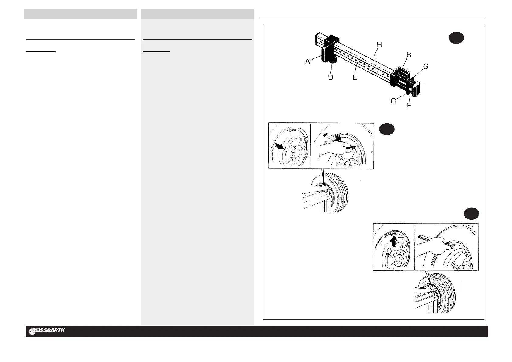
CALIBRO (Fig.21a)
A: CORSOIO CALIBRO BASE
B: TESTINA CALIBRO POSIZIONE PESI
C: PINZA ESTERNA
D: POMELLO A VITE
E: TARGHETTA MILLIMETRATA
F: ESPULSORE
G: PINZA INTERNA PER FISSAGGIO PESO
H: IMPUGNATURA CON SEDE TARGHETTA
La macchina è fornita di un CALIBRO SPECIALE per la programmazione
ed il fissaggio dei pesi adesivi su cerchi in alluminio e lega leggera.
Questo calibro, previsto per l’utilizzo con i programmi alu-2 e alu-3 (peso
esterno sul canale), permette di determinare con la massima precisione (e
secondo la conformità del cerchio) la posizione esatta di fissaggio del peso
adesivo.
Osservare le figure 21a-21b e 21c e procedere come segue:
» programmare la macchina su ALU-2 (peso esterno sul canale) premendo
ripetutamente il tasto MODE (10-fig.19);
» posizionare il calibro con la base (A) sul bordo interno del cerchio;
» facendo scorrere la base A sul cursore millimetrato (E) portare la pinza
esterna (C) sulla posizione desiderata e ottimale di fissaggio peso;
» fissare la base (A) con l’apposito pomello a vite (D);
» leggere la misura in mm e impostarla tramite tastiera sulla larghezza
cerchio; attenzione: impostare la misura in mm (led acceso);
» fare un lancio di equilibratura: usciranno i valori del peso ( interno ed
esterno);
» portare in posizione la ruota e montare il peso (letto sul display esterno)
sulla pinza esterna (C);
» portare la base (A) sul bordo del cerchio (ore 12) e fissare il peso tramite
l’espulsore (F) (vedere fig.21b);
» portare in posizione la ruota e montare il peso (letto sul display interno)
sulla pinza interna (G);
» portare la testina calibro (B) sul bordo del cerchio e fissare il peso tramite
l’espulsore (F) (ved. fig.21c).
N.B.: Per il programma ALU-3 la procedura esterna rimane la stessa; per
l’interno fissare il peso a molletta sul bordo cerchio.
PROGRAMMING AND FITTING ADHESIVE
WEIGHTS WITH THE SPECIAL GAUGE FOR
ALUMINIUM OR LIGHT ALLOY RIMS
GAUGE (Fig.21a)
A: GAUGE BASE CURSOR
B: WEIGHT POSITIONING GAUGE HEAD
C: OUTSIDE CLAW
D: SCREW KNOB
E: SCALE PLATE IN MILLIMETRES
F: EXTRUDER
G: INSIDE CLAW FOR FIXING WEIGHTS
H: GRIP WITH SCALE PLATE INSERT
The machine is equipped with a SPECIAL GAUGE for programming and
fixing the adhesive weights on aluminium and light alloy rims.
The gauge is for use with alu-2 and alu-3 programs (external weight on the
groove) and gives greatest precision (accounting for rim conformity to stan-
dard) for obtaining the exact position for attaching the adhesive weight.
Observe figures 21a-21b and 21c and proceed as follows:
» program the machine in ALU-2 (external weight on groove) by repeat-
edly pressing the MODE key (10-fig.19);
» position the gauge with the base (A) on the internal edge of the rim;
» slide the base A on the mm cursor (E) and bring the external pliers (C)
into the desired and best position for fixing the weight;
» fix the base (A) using the knob screw (D);
» read the measurement in mm and set same on rim width through key-
board; warning: set measurement in mm (LED lit up);
» launch balancing run; the weight values will be given (internal and exter-
nal);
» bring the wheel into position and fix weight (read from external display)
on external pliers (C);
» bring the base (A) to the edge of the rim (12 o’clock position) and fix the
weight using the knockout (F) (see fig.21b);
» bring the wheel into position and fix the weight (read from internal) on
the internal pliers (G);
» bring the gauge head (B) to the edge of the rim and fix the weight using
the knockout (F) (see fig.21c).
N.B.: For the ALU-3 program the external procedure is the same; for the
internal procedure fix the clipped weight on the rim edge.