Do you have a question about the BEKA BA327C and is the answer not in the manual?
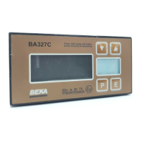
Details on the four front panel push-button controls and their functions in display mode.
Information on the EC-Type Examination Certificate and compliance with ATEX Directive.
Specifications for the 4/20mA input current and intrinsic safety parameters.
Details on the certified EEx ia IIC T5 rating and applicable hazardous area zones.
Description of the information found on the instrument's certification label.
Guidance on connecting indicators in series with intrinsically safe 4/20mA current loops.
Methods for providing remote indication within hazardous areas using intrinsically safe interfaces.
Considerations for selecting the installation location and environmental limits.
Step-by-step instructions for mounting the indicator into a panel.
Information on compliance with the European EMC Directive and wiring recommendations.
Overview of the main programmable functions and cross-references to detailed sections.
Function to activate or deactivate the square root extractor for linearization.
Setting the resolution of the least significant display digit for improved readability.
Procedure for positioning or turning off the dummy decimal point.
Method for calibrating zero and span using an external current source.
Method for calibrating zero and span using internal references without external source.
Setting the mains frequency for maximum AC rejection.
Procedure for periodically calibrating the indicator's internal 4mA and 20mA references.
Configuring the P push-button to display input current in mA or as a percentage.
Setting a four-digit code to protect access to programmable functions.
Description of how over and under-range conditions are indicated on the display.
Step-by-step example of calibrating the indicator using an external current source.
Step-by-step example of calibrating the indicator using internal references.
Procedure for diagnosing and resolving faults that occur during initial setup.
Procedure for diagnosing and resolving faults that occur after the instrument is operational.
Information on servicing and recommendations for returning faulty instruments.
Recommendations for regular checks of the instrument's mechanical condition and calibration.
Details on the product guarantee period and return procedures for faulty units.
Invitation for customer feedback and suggestions for product improvement.
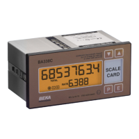
Information on the scale card used to display measurement units and how to mark it.
Details on the optional thermally printed tag number supplied on the rear panel.
Description of the galvanically isolated single pole solid state switch alarm output.
Intrinsic safety parameters for alarm outputs certified as simple apparatus.
Overview of programming the main menu to include additional alarm functions.
Function to enable or disable alarm functionality without altering parameters.
Procedure for adjusting alarm setpoints, defining the input current range.
Defining whether an alarm operates as a high or low alarm.
Configuring alarm outputs to be normally open or normally closed.
Adjusting the alarm hysteresis value, which affects when the alarm resets.
Setting a delay for alarm activation to prevent nuisance tripping.
Setting a time delay for the alarm output after it has been accepted.
Enabling direct access to alarm setpoints from display mode with optional security.
Procedure for adjusting alarm setpoints directly from the indicator's display mode.
Information on the optional sixteen-point lineariser for non-linear signal compensation.
Method for calibrating the lineariser using an external current source for traceability.
Method for calibrating the lineariser using internal references without an external source.
Description of the software accessory for zeroing the display, primarily for weighing systems.
Overview of the two types of backlights available: loop powered and separately powered.
Details on the separately powered backlight, its certification, and connection requirements.
Details on the loop powered backlight, its connection in series with the indicator.
Overview of Factory Mutual approval for intrinsic safety and nonincendive applications.
Entity parameters for 4/20mA input in intrinsically safe circuits.
Approval details for nonincendive applications in Class I, Division 2 locations.
Factory Mutual approval status for accessories like Alarms and Display backlight.
FM approval for fitting alarm cards with single pole solid state outputs.
Approval status for separately powered and loop powered backlights.
Overview of the IECEx global certification scheme for explosion protected products.
Details of the IECEx Certificate of Conformity number and marking for the indicators.
Installation requirements for IECEx and ATEX approvals, referencing EN 60079-14.
| Brand | BEKA |
|---|---|
| Model | BA327C |
| Category | Measuring Instruments |
| Language | English |