14
7. CALIBRATION EXAMPLES
The following examples illustrate the two ways in
which a BA327C or BA328C indicator may be
calibrated.
7.1 Using an external calibrator
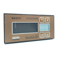
A BA327C is required to display:
-50.0 with a 4mA input
1050.0 with a 20mA input
from a linear transducer. Maximum display
resolution is required, the frequency of the mains
supply is 50Hz and the existing security code is
1209. In the operating mode the indicator is
required to display the input current as a
percentage of span when the P push-button is
operated.
Step 1 Connect indicator to calibrator
Connect the indicator to an accurate
external current source. Terminal 1
positive. The indicator will automatically
perform the initialisation routine
described in section 2, and then display
the input current using the existing
calibration information.
Step 2 Enter programming mode
With an input current between 4 and
20mA put the indicator in the
programming mode by simultaneously
pressing P and E. The indicator will
respond by displaying 'COdE'. Press P
to clear this prompt and set the display to
the security code 1209 using the Up,
Down and P push-buttons. Pressing E
will enter the code, and after a few
seconds during which the decimal points
will be scrolled, the first parameter 'root'
in the main menu will be displayed.
Step 3 Square root extraction
With 'root' displayed, press P which will
reveal the root extractor status. The root
extractor can be turned on or off by the
Up or Down buttons. Select 'OFF', and
press E to return to the main menu.
Step 4 Select frequency of max rejection
Scroll though the main menu until 'Cond'
is displayed. Enter the sub-menu by
pressing P twice and select the 'FrE'
function. Using the Up or Down buttons
select '50', and then press E twice to
return to the main menu.
Step 5 Define function of P push-button
Select 'C--P' from the main menu and
press P to reveal the function of the P
button in the display mode. Select
percentage 'PC' and return to the main
menu by pressing E
Note: Because an input current display
in milliamps is not required, it is not
necessary to calibrate the two internal
references.
Step 6 Position dummy decimal point
Scroll though the main menu until 'd.P.'
is displayed and then press P. Using
the Up and Down push-buttons position
the dummy decimal point in front of the
least significant digit.
Press E to return to the main menu.
Step 7 Calibrate the display
Scroll through the main menu until
'CAL' is displayed. Press P and the
indicator will request a 4mA input by
displaying 'ZErO'. Set the input current
to 4.0000 ± 0.0004mA and press P
again which will reveal the existing zero
display. Using the Up, Down and P
push-buttons enter the required zero
display of -50.0 Press E to return to
the 'ZErO' prompt.
Press the
Up push-button and the
indicator will request a 20mA input by
displaying 'SPAn'. Set the input
current to 20.0000 ± 0.0004mA and
again press P which will reveal the
existing span display. Using the Up,
Down and P push-buttons enter the
required display of 1050.0
Press E twice to return to the main
menu.
Step 8 Return to the display mode
Return to the display mode by pressing
'E'.
7.2 Using the internal calibrator
As in 7.1 the BA327C is required to display:
-50.0 with a 4mA input
1050.0 with a 20mA input
from a linear transducer. Maximum display
resolution is required, the frequency of the mains
supply is 50Hz and the existing security code is
1209. In the operating mode the indicator is
required to display the input current in milliamps
when the P push-button is operated.
This example assumes that the internal references
have been routinely calibrated.