3
1. DESCRIPTION
The BA327C and BA328C are 4½ digit intrinsically
safe loop powered digital indicators which display
the current flowing in a 4/20mA loop in engineering
units. Both instruments introduce less than a 1.1V
drop which allows them to be installed into almost
any 4/20mA current loop. No additional power
supply or battery is required.
The two indicators are electrically similar, but have
different size displays and enclosures.
Model Display height Bezel size
BA327C 10mm 96 x 48mm
BA328C 20mm 144 x 72mm
The main application of the BA327C and BA328C
is to display a measured variable or control signal
in a hazardous process area. The zero and span
of the display are independently adjustable so that
the indicators can be calibrated to display any
variable represented by the 4/20mA current, e.g.
temperature, flow, pressure or level.
The BA327C and BA328C have been certified
intrinsically safe by ITS Testing and Certification
Ltd to the European ATEX Directive 94/9/EC. The
EC-Type Examination certificate specifies that
under fault conditions the voltage, current and
power at the input terminals of each instrument will
not exceed those specified for simple apparatus in
Clause 5.4 of EN50020:1994.
The BA327C and BA328C are also FM and cFM
approved for use in the USA and Canada, these
approvals are described in Appendix 1.
International IECEx certification is described in
Appendix 2.
2. OPERATION
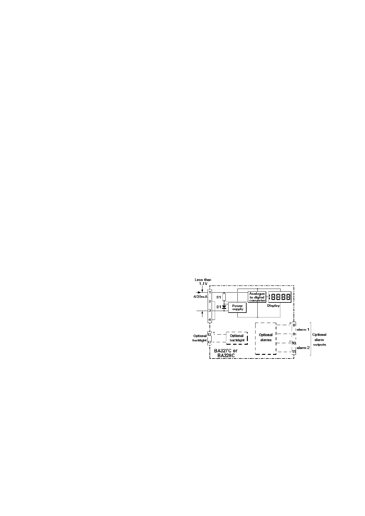
Fig 1 shows a simplified block diagram of both
models. The 4/20mA input current flows through
resistor R1 and forward biased diode D1. The
voltage developed across D1, which is relatively
constant, is multiplied by a switch mode power
supply and used to power the instrument. The
voltage developed across R1, which is proportional
to the 4/20mA input current, provides the input
signal for the analogue to digital converter.
Each time a 4/20mA current is applied to the
instrument, initialisation is performed. After a short
delay the following display sequence occurs:
-1.8.8.8.8 Display test in which
all segments of the
display are activated
for 0.5 seconds.
Blank display For 0.5 seconds.
Decimal points For 3 seconds.
cycled
Input current Using calibration
display in information stored in
engineering instrument memory.
units.
Fig 1 Simplified block diagram of BA327C and
BA328C