8 AFTER SALES SUPPORT
support@tdcusainc.com 1800 599 8898
MODEL: 21224-21 PRODUCT CODE: 1958 05/2021
AFTER SALES SUPPORT 9
1800 599 8898 support@tdcusainc.com
MODEL: 21224-21 PRODUCT CODE: 1958 05/2021
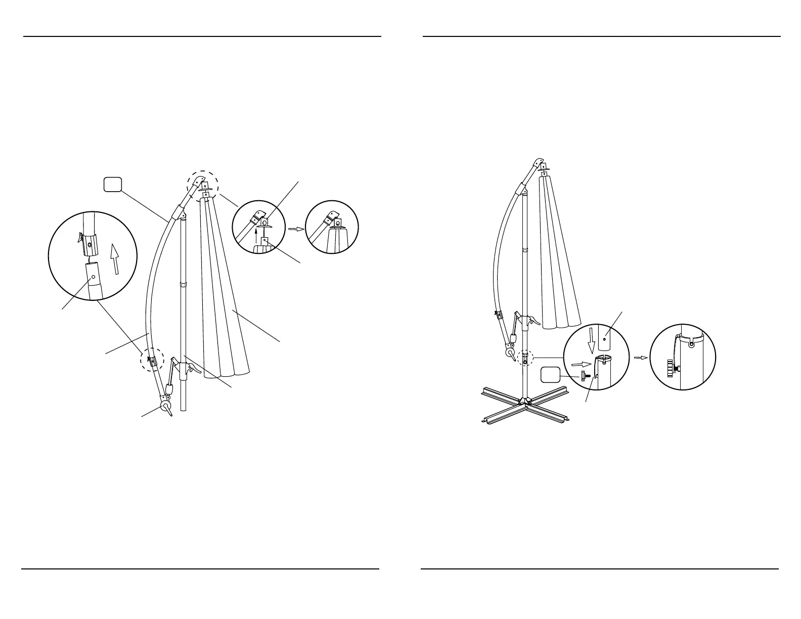
STEP 2:
Place the Umbrella Frame (A) in the correct orientation as illustrated above,
with the pole placed in between the umbrella canopy and the canopy
arm. Turn the crank handle clockwise until the line inside the canopy arm
tightens; see Figure 1. Connect the two ends of the canopy arm together
using the push pins found on either side of the canopy arm; see Figure
2. Use the push pins to connect the top of the umbrella canopy to its
housing; see Figure 3.
*Please see descriptions for individual pieces that make up each part
found within the following illustrations to better understand the
instructions to complete assembly.
*Place a counterweight such as an offset umbrella base (not
included) that can be filled with water or sand or triangular
weight bases (not included) before proceeding further. An offset
umbrella base should be able to hold 100lbs. of sand or water or
4 triangular weight bases, minimum 25lbs. each, is recommended
to maintain product stability; especially while umbrella canopy is
open.
Assembly Instructions Assembly Instructions
STEP 3:
Place the pole of the Umbrella Frame (A) inside of the Bottom Pole (B) so
that the prongs fit within groves at the top of part B; see Figure 4. Insert
Locking Knob (E) through band found at the top of part B and into the
screw threading of this part; see Figure 4. Tighten the Locking Knob
(E) until pressed against the pole of the Umbrella Frame (A) enough to
hold it in place; see Figure 5. Over tightening may dent or chip away at
the protective coating of the Umbrella Frame (A).
A
Fig.1
Fig.2 Fig.3
Umbrella
Canopy
Push Pin
Housing
Push Pin
Crank
Pole
Canopy
Arm