12 AFTER SALES SUPPORT
support@tdcusainc.com 1800 599 8898
MODEL: 22096-21 PRODUCT CODE: 44964 05/2021
AFTER SALES SUPPORT 13
1800 599 8898 support@tdcusainc.com
MODEL: 22096-21 PRODUCT CODE: 44964 05/2021
USA USA
USAUSA
Assembly Instructions
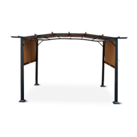
STEP 5:
Place assembled Crossbeams (B) on top of two standing Poles (A
1
& A
2
).
For a consistent look, place Crossbeams (B) on Poles (A
1
& A
2
) so that the
head of bolts used to hold these parts together are facing outward;
see Figure 6. Please note that A
1
will be on your left and A
2
on your
right when facing these parts from outside the pergola. Insert two
Bolts M6x65mm (EE) through either end of assembled Crossbeams (B)
and into the tops of Poles (A
1
& A
2
); see Figure 7.
See Figure 9 for the correct orientation of A
2
so that the female-
bolt inserts intended for part F are facing in the correct direction.
See Figure 8 for the correct orientation of A
1
, before assembly of
the crossbeams to A
1
and A
2
is complete.
Insert Bolt M6x15mm (BB) through Support (I) and into female-bolt
insert beneath assembled Crossbeams (B); see Figure 8. Insert second
Bolt M6x15mm (BB) through opposite ends of both Supports (I) and
into both Poles (A
1
& A
2
).
Repeat these steps to assemble second set of Poles (A
1
& A
2
) with
Crossbeams (B).
2X
EE
B
B
A
2
A
1
Fig. 7
Fig. 8
Fig. 9
BB
I
I
BB
I
I
Female-Bolt
Insert
Fig. 6
*Do not ghten screws down completely during
this poron of assembly.
Assembly Instructions
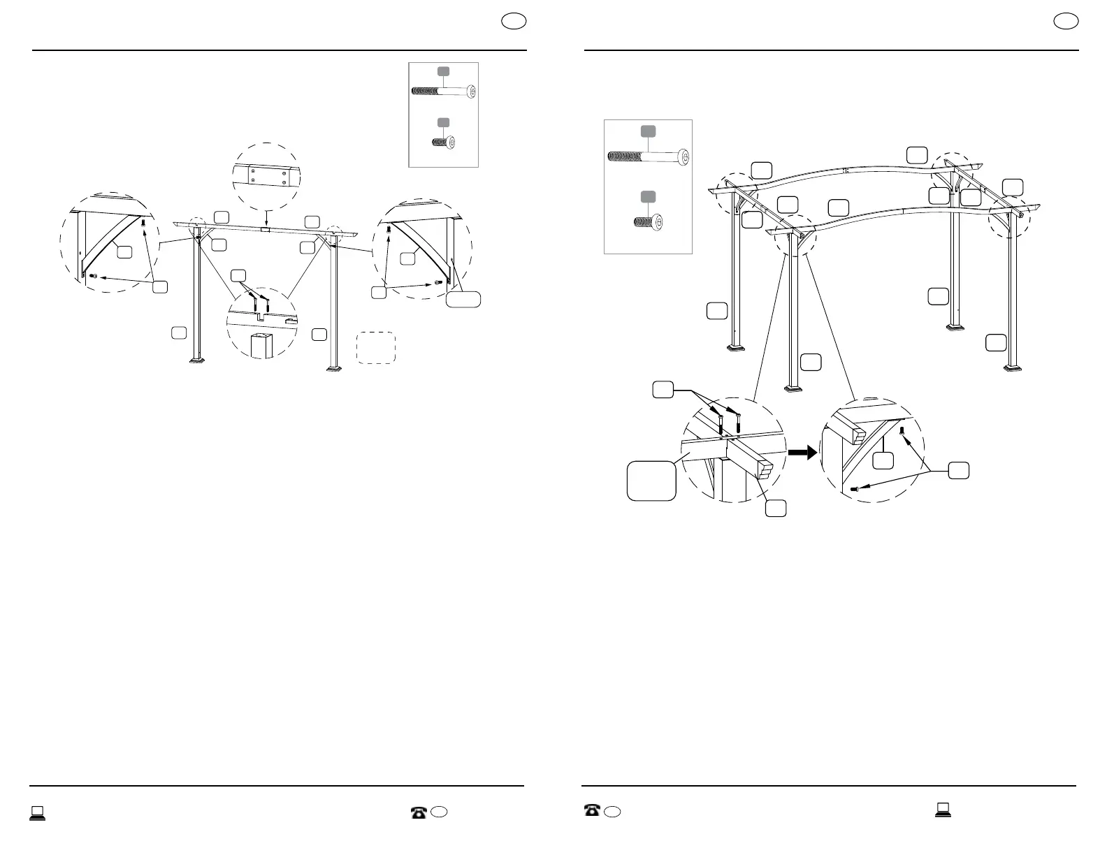
STEP 6:
Insert cutout notch of assembled Crossbeams (C & D) into cutout notch
of Crossbeams (B). Insert two Bolts M6x65mm (EE) through either end of
assembled Crossbeams (C & D) and into the tops of all Poles (A
1
& A
2
); see
Figure 10.
Repeat these steps to connect all crossbeams to remaining Poles (A
1
& A
2
).
Insert Bolt M6x15mm (BB) through Support (I) and into female-bolt insert
beneath assembled Crossbeams (C & D). Insert second Bolt M6x15mm
(BB) through opposite ends of Supports (I) and into Poles (A
1
& A
2
); see
Figure 11.
C
D
D
B
B
B
A
2
A
1
A
2
A
1
EE
BB
B
I
Assembled
Crossbeam
C & D
Fig. 10 Fig. 11
C
B
*Do not ghten screws down completely during this
poron of assembly.
EE
(8) M6X65 mm Screw
BB
(8) M6X15 mm Screw
EE
(8) M6X65 mm Screw
BB
(8) M6X15 mm Screw