Do you have a question about the Belden HIRSCHMANN RSP20 and is the answer not in the manual?
Explains warning symbols and danger levels used in the manual.
Covers general handling, operation, and maintenance safety guidelines.
Details requirements for product usage to ensure safety and compliance.
Specifies environmental and location requirements for safe device installation.
Guidelines for managing cable stress to prevent connection issues.
Information regarding access and care for the device casing.
Defines the necessary qualifications for personnel working on the device.
Emphasizes compliance with applicable electrical installation safety standards.
Procedures for proper grounding of the device for electrical safety.
Explains how to connect the shield of twisted pair cables to the ground.
Lists essential checks and compliance for connecting electrical wires.
Outlines voltage and fuse requirements for signal contact connections.
Details voltage, wire diameter, and connection requirements for power supply.
Directive on electromagnetic compatibility for devices.
Directive restricting hazardous substances in electrical equipment.
Directive on electrical equipment safety for specific voltage limits.
Directive for equipment intended for potentially explosive atmospheres.
UK regulation restricting hazardous substances in electrical equipment.
UK regulations for electromagnetic compatibility.
UK regulations for electrical equipment safety.
UK regulations for equipment in potentially explosive atmospheres.
Information on LED or LASER components compliance with IEC 60825-1.
FCC compliance statement and operating conditions.
Contact details for Belden in the U.S.
Guidelines for proper disposal of electronic waste.
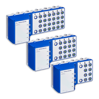
Details the device's design for industrial automation, reliability, and flexibility.
Explains how device names correspond to product codes and characteristics.
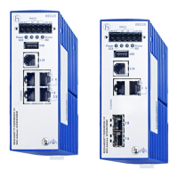
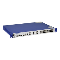
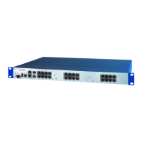
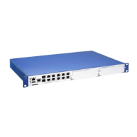
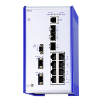
Illustrates the front and rear views of the device and identifies key components.
Describes different supply voltage options (K9, KK, TT, CC) and their connection types.
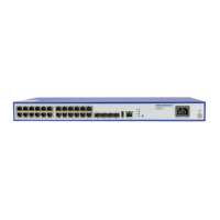
Details the available Ethernet ports, including twisted pair and fiber optic options.
Explains the meaning of device status and port status LEDs.
Describes the V.24 serial interface and the SD card interface for management.
Details the potential-free relay contact for external device control or monitoring.
Procedure to verify all items are present and undamaged.
Steps for inserting an SD card for configuration and software loading.
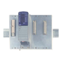
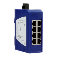
Covers mounting the device on a DIN rail and proper grounding procedures.
Instructions for installing SFP transceivers into the device slots.
Guides for connecting supply voltage and signal contact terminal blocks.
Steps to power on and begin operating the device.
Recommendations for connecting data cables in noisy environments.
Guidance on using the inscription label for device identification.
Outlines methods for configuring IP addresses (V.24, HiView, DHCP, etc.).
Lists the factory default settings for IP address, passwords, and port configurations.
Procedure for the first login and changing the default password for security.
Explains how device software versions affect upgrade options and features.
How to monitor ambient temperature and interpret internal device temperature readings.
Covers device durability, relay wear, software updates, and ventilation.
Step-by-step instructions for safely removing the device from its mounting.
Procedure for safely de-installing SFP transceivers from the device.
Comprehensive technical specifications including dimensions, weight, and supply voltages.
Visual representations of the device dimensions for installation planning.
Details the device's compliance with electromagnetic compatibility and immunity standards.
Specifies maximum cable lengths and performance for fiber optic and twisted pair ports.
Lists power consumption and output ratings for different device variants.
Information on included items, order numbers, and recommended accessories.
Lists the various technical standards and regulations the device complies with.
Provides contact details for technical questions and support resources.
Outlines consulting, training, and support services offered by Hirschmann.