800-543-9038 USA 866-805-7089 CANADA 203-791-8396 LATIN AMERICA / CARIBBEAN
Accessories
l-
mm
n
1
mm wr
n
3442-00001 Gland (needed for additional wires
1
7-
1 Gasket for Gland (needed for additional wires
NOTE
When using AFBUP N4(H), AFBUP-S N4(H), AFXUP N4, AFXUP-S N4 actuators, only use
ccessories listed on this pa
e.
For actuator wiring information and diagrams, refer to Belimo Wiring Guide
Typical Specification
On/Off sprin
return damper actuators shall be direct coupled type which require
o crank arm and linka
e and be capable of direct mountin
to a
ackshaft up to a
1.05” diameter. The actuators must be desi
ned so that they may be used for either
lockwise or counterclockwise fail-safe o
eration. Actuators shall be
rotected
from overload at all an
les of rotation. If required, two SPDT auxiliary switch shall
e provided havin
the capability of one bein
ad
ustable. Actuators with auxiliary
switches must be constructed to meet the re
uirements for Double Insulation so
an electrical
round is not required to meet a
ency listin
s. Actuators shall be
ULus A
roved and have a 5
ear warrant
, and be manufactured under I
9001
International Qualit
Control Standards. Actuators shall be as manufactured b
Belimo
FBUP N4
H
, AFBUP-
N4
H
, AFXUP N4, AFXUP-
N4
NEMA 4, On/Off, Sprin
Return, 24 to 240 VAC
AFBUP N4(H)
AFBUP-S N4(H)
AFXUP N4
AFXUP-S N4
066
4
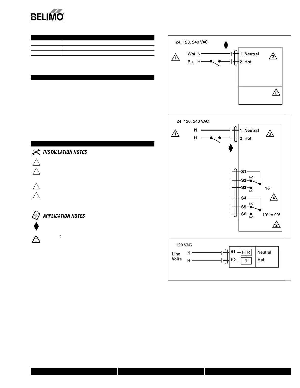
On/Off Wirin
Wht
Blk
AFBUP-S N4(H)
AFXUP-S N4
W067
AFBUP-
N
Auxiliary
witche
F-NF N4H 12
V h
t
EMA 4 Heater
Wiring Diagrams
1
rov
e over
oa
protect
on an
sconnect as requ
re
2
A
TI
N
qu
pment
ama
e
ctuators may
e connecte
n para
e
.
ower consumpt
on an
nput
mpe
ance must
e o
serve
.
o ground connection is required
or end position indication, interlock control,
an startup, etc.,
AFBUP-S N4(H), AFXUP-S N4 incorporates two built-in auxiliary switches:
2 x SPDT, 3A
0.5A
@250 VAC, UL Approved, one switch is fi xed at +10°,
one is ad
ustable 10° to 90°
Meets cULus requirements without the need of an electrical ground con
nect
on.
Live Electrical Components!
During installation, testing, servicing and troubleshooting o
this product, it may be
necessary to work with live electrical components. Have a quali
ed licensed electrician or other
individual who has been properly trained in handlin
live electrical components per
orm these
tasks. Failure to
ollow all electrical sa
ety precautions when exposed to live electrical compo-
nents could result in death or serious injury
N40103 - 09/11 - Subject to change. © Belimo Aircontrols (USA), Inc.
 Loading...


