800-543-9038 USA 866-805-7089 CANADA 203-791-8396 LATIN AMERICA / CARIBBEAN
7
AFB24-SR, AFB24-SR-S, AFX24-SR, AFX24-SR-S
roportional, Sprin
Return, 24 V, for 2 to 10 VDC or 4 to 20 mA Control Si
nal
or
ue min. 180 in-lb,
or control o
air dam
er
A
l
cat
o
or proportional modulation of dampers in HVAC systems. Actuator sizing should be
one in accordance with the dam
er manu
acturer’s s
eci
ications.
he actuator is mounted directl
to a dam
er sha
t u
to 1.05” in diameter b
means
f its universal clamp. A crank arm and several mounting brackets are available for
pplications where the actuator cannot be direct coupled to the damper sha
t
he actuator o
erates in res
onse to a 2 to 10 VDC, or with the addition of a 50
esistor, a 4 to 20 mA control in
ut from an electronic controller or
ositioner. A 2 to
10 VDC feedback si
nal is provided for position indication. Not to be used for a
master-slave a
lication
O
eratio
he AFB and AFX series actuators provide true sprin
return operation for reliable fail-
afe application and positive close-off on air ti
ht dampers. The sprin
return system
rovides constant tor
ue to the dam
er with, and without,
ower a
lied to the
t
t
r
he AFB and AFX series provides 95° o
rotation and is provided with a
raduated
os
t
on
n
cator s
ow
ng 0° to 95°.
he AFB24-SR and AFX24-SR uses a brushless DC motor which is controlled by an
pplication Specific Inte
rated Circuit
ASIC
and a microprocessor. The
microprocessor provides the intelligence to the ASIC to provide a constant rotation rate
nd to know the actuator’s exact fail-safe
osition. The A
I
monitors and controls
the brushless D
motor’s rotation and provides a digital rotation sensing function to
revent dama
e to the actuator in a stall condition. The actuator may be stalled
nywhere in its normal rotation without the need o
mechanical end switches
he AFB24-SR-S and AFX24-SR-S versions are provided with two built-in auxiliary
witches. These SPDT switches provide safety interfacin
or si
nalin
, for example, for
an start-up. The switching
unction at the
ail-sa
e position is
ixed at +10°, the other
witch function is adjustable between +10° to +90°. The AFB24-
R, AFB24-
R-
,
FX24-
R and AFX24-
R-
actuator is shipped at +5°
5° from full fail-safe
to
rovide automatic compression a
ainst damper
askets for ti
ht shut-off
ATTENTI
N
AFB24-SR
-S
and AFX24-SR
-S
annot
e tan
em mounte
on t
e
ame dam
er or valve shaft.
nl
n
ff and MFT AF models can be used for tandem
mount app
cat
ons.
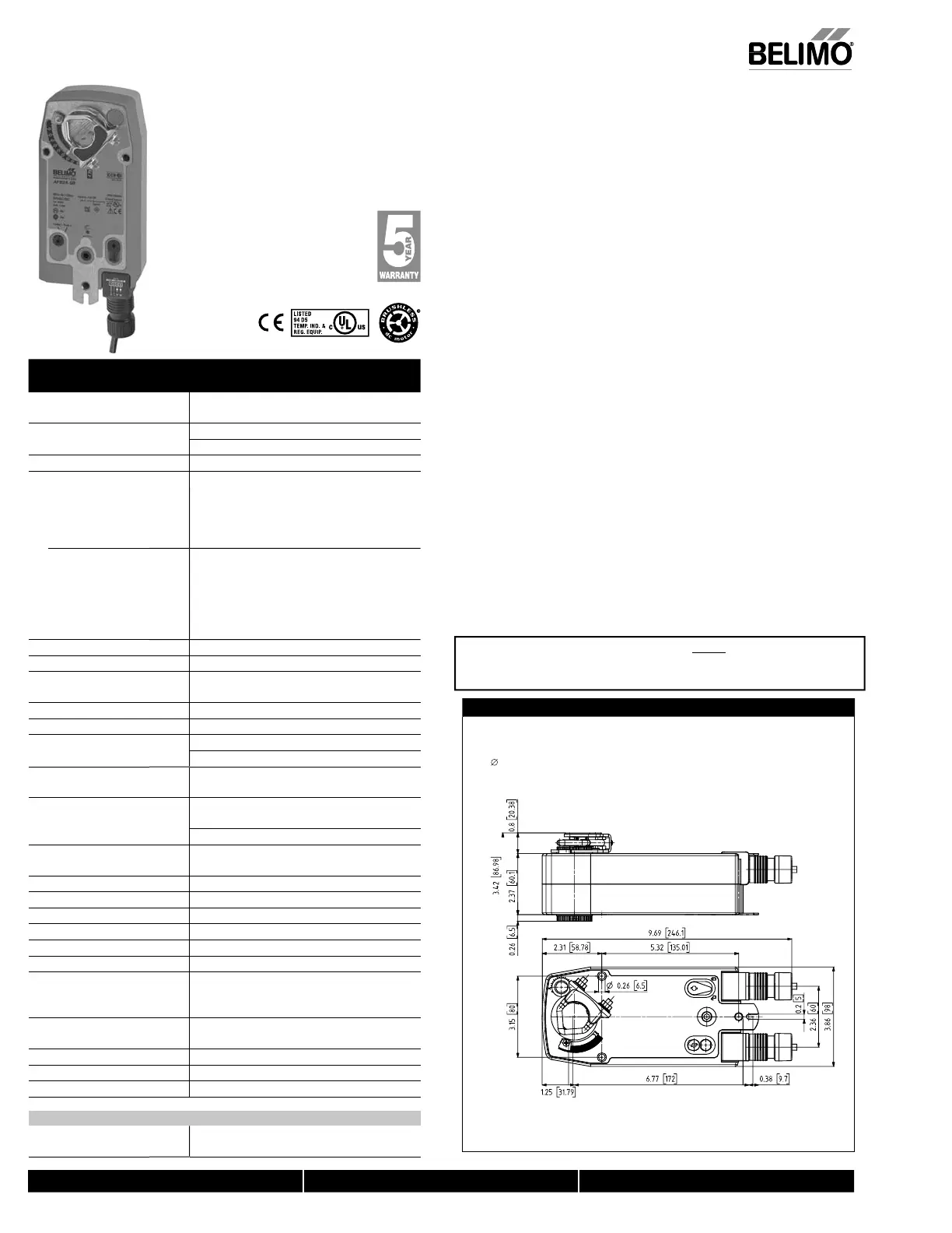
Dimensions (Inches [mm])
K7-2 (supplied)
1/2" Centered
(Default)
3/4" Centered
(Field Selectable)
1.05" Centered
(Field Selectable)
WAFBNFBDim
Technical Data AFB24-SR, AFB24-SR-S,
AFX24-SR, AFX24-SR-S
Power su
l
24 VAC ±20%, 50/60 Hz
24 VD
+20%
-10
Power consumption running
.5
holdin
Trans
ormer sizing 8.5 VA (class 2 power source
Electrical connectio
FB..
ft, 18 GA appliance cable, 1/2" conduit
onnec
or
-S models: two 3
t, 18 gauge appliance cables
ith 1
2”
n
it
nn
t
r
...
t [1m], 10 ft [3m] or 16 ft [5m] 18
A
appliance or plenum cables, with or without 1
2”
onduit connecto
-S m
dels: Two 3
t
1m
, 10
t
3m
or
6 ft
5m
appliance cables, with or without 1/2"
on
u
t connectors
Overload
rotectio
electronic throughout 0 to 95° rotation
Operatin
ran
e Y 2 to 10 VDC
4 to 20mA
In
ut im
edanc
00 k
for 2 to 10 VDC
0.1 mA
f
r 4 t
2
mA
Feedback out
ut
2 to 10 VDC (max. 0.5 mA)
Tor
ue
80 in-lb
20 Nm
minimu
Direction o
rotatio
prin
eversible with CW/CCW mountin
mo
o
evers
e w
t
u
t-
n sw
tc
echanical an
le o
rotatio
95°
ad
ustable with mechanical end stop, 35° to
95°
Runnin
time
pr
n
20 seconds @ -4°F to 122°F
-20°C to 50°C
60 seconds
-22°F
-30°
m
r
n
os
t
on
n
cat
o
sua
n
cator, 0° to 95°
0° is
ull spring return position)
n
l
v
rri
mm hex crank (
₁₆
Allen), supplie
Humidity
ax. 95% RH non-condensin
m
ent temperatur
22°F to 122°F
-30°
to 50°
tora
e temperature
40°F to 176°F
-40°
to 80°
Housin
ema 2, IP54, Enclosure T
e
Housin
materia
zinc coated metal and plastic casin
ency
st
n
ULus acc. to UL60730-1A/-2-14, CAN/CSA
60730-1:02,
E acc. to 2004
108
E
&
2
E
N
i
l
v
l ≤40dB
A
motor @ 95 seconds
≤62
spr
n
return
ervicing
int
n
n
r
Quality standar
1
Weigh
4.6 lbs (2.1 kg); 4.9 lbs (2.25 kg) with switches
† Rated Impulse Voltage 800V, Type of action 1.AA (1.AA.B for -
version),
ontrol Pollution Degree 3.
FB24-
R-
, AFX24-
R-
Auxiliary switches 2 x
PDT 3A
0.5A
250 VA
, UL approved
one set at +10°, one ad
ustable 10° to 90
N40103 - 09/11 - Subject to change. © Belimo Aircontrols (USA), Inc
 Loading...


