800-543-9038 USA 866-805-7089 CANADA 203-791-8396 LATIN AMERICA / CARIBBEAN
Torque min. 180 in-lb, for control of air dampers
Applicatio
For
n
ff, fail-safe control of dampers in HVA
systems. Actuator sizin
should be
done in accordance with the damper manufacturer’s specifications. Control is On/Off
from an auxiliar
contact, or a manual switch.
The actuator is mounted directl
to a dam
er shaft u
to 1.05” in diameter b
means
f its universal clamp. A crank arm and several mounting brackets are available for
lications where the actuator cannot be direct cou
led to the dam
er shaft
O
eratio
The AFB N4
H
and AFX N4 series actuators provide true sprin
return operation for
eliable fail-safe application and positive close off on air ti
ht dampers. The sprin
eturn s
stem
rovides constant tor
ue to the dam
er with, and without,
ower
pp
e
to t
e actuator
The AFB N4(H) and AFX N4 series provides 95° of rotation and is provided with a
graduated position indicator showing 0° to 95°
The actuator ma
be stalled an
where in its normal rotation without the need of
m
n
n
w
t
.
The AFB24-
N4(H), AFX24-
N4 version are provided with two built-in auxiliary
switches. These
PDT switches are provided for safety interfacing or signaling, for
example,
or
an start-up. The switchin
unction at the
ail-sa
e position is
ixed at
+10°, the other switch
unction is ad
ustable between +10° to +90°.
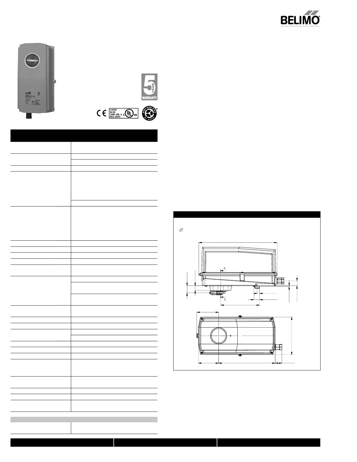
Dimensions (inches [mm])
6.77” [172]
Clamp Congurations
1/2” Field Selectable 3/4” Centered 1.05” Centered
(Default) (Field Selectable)
12.99” [330]
6.45” [163.9]
0.39” [10]
0.92” [23.4]
3.62” [92.1]
9.37” [238] 1.12” [28.5]
3.36” [85.2]
3.5” [0.14]
0.81” [20.5]
1.17” [29.8]
0.79” [20]
D312_Confi
Technical Data AFB24 N4(H), AFB24-S N4(H),
AFX24 N4, AFX24-S N4
Power supply 24 VAC ± 20% 50/60 H
24 VDC +20% / -10%
Power consumption runnin
5 W / heater 25 W
holdin
2.5
Transformer sizing 7.5 VA (class 2 power source)
heater 25 VA
Electrical connectio
...
4
3 ft, 18 GA appliance cable, 1/2” conduit
connecto
-S m
dels: Two 3 ft, 18
au
e appliance cables
with 1
2”
n
it
nn
t
r
eater (N4H) terminal block, 26-16 GA
AFX... N4
ft [1m], 10 ft [3m] or 16 ft [5m] 18 GA
appliance cable, with or without 1
2” conduit
connec
o
-S m
dels: Two 3
t [1m], 10
t [3m] or
16 ft [5m] appliance cables with or without 1/2”
n
t
nn
t
r
verload
rotectio
e
ectron
c t
rou
out 0 to 95° rotat
on
ontro
on
of
Tor
ue 180 in-lb
20 Nm
minimu
Direction of rotatio
sprin
reversible with CW/CCW mountin
in housin
echanical an
le of rotatio
95°
ad
ustable with mechanical end stop, 35° to
95°
Runnin
time
mo
or
< 75 second
sprin
20 seconds @ -4°F to 122°F
-20°C to 50°C
;
< 60 seconds @ -22°F [-30°C
pr
ng
w
t
eater
20 seconds
-4°F to 122°F [-20°
to 50°
],
<60 seconds
-49°F
-45°
Position indicatio
visual indicator, 0° to 95
(0° is
ull spring return position)
anual overrid
5 mm hex crank
₁₆
Allen
, supplie
Humidit
max. 95% RH non-condensin
Ambient temperatur
-22°F to 122°F
-30°
to 50°
with h
t
-49°F to 122°F
-45°
to 50°
tora
e temperature -40°F to 176°F
-40°C to 80°C
ous
n
ype 4,
4,
6
ous
ng mater
a
po
ycar
onate
gency
st
ngs
cULus acc. to UL60730-1A/-2-14,
AN
A E60730-1:02,
E acc. to
2004
108
E
& 2006
95
E
Noise level <50dB
A
motor
75 seconds
≤62dB(A) spring return
ervicin
m
int
n
n
r
uality standar
I
9001
Wei
h
9.7 lbs
4.4 k
; 10 lbs
4.5 k
with switches;
10.5 lbs (4.8 kg) with heate
† Rated Impulse Volta
e 800V, Type of action 1.AA
1.AA.B for -S version
, Control Pollution De
ree 4.
FB24-S N4
H
, AFX24-S N
ux
ar
sw
tc
es 2 x SPDT 3A
0.5A
@ 250 VAC, UL approve
one set at +10°, one a
usta
e 10° to 90
AFB24 N4(H), AFB24-S N4(H), AFX24 N4, AFX24-S N
EMA 4, On/Off, Sprin
Return, 24
N40103 - 09/11 - Subject to change. © Belimo Aircontrols (USA), Inc
 Loading...


