800-543-9038 USA 866-805-7089 CANADA 203-791-8396 LATIN AMERICA / CARIBBEAN
2
Accessories
l-
mm
n
1
mm wr
n
3442-00001 Gland (needed for additional wires
1
7-
1 Gasket for Gland (needed for additional wires
NOTE
When using AFB24 N4(H), AFB24-S N4(H), AFX24 N4, AFX24-S N4 actuators, only use
ccessories listed on this pa
e.
For actuator wiring information and diagrams, refer to Belimo Wiring Guide
Typical Specification
FB24 N4
H
, AFB24-
N4
H
, AFX24 N4, AFX24-
N4
EMA 4, On/Off, Sprin
Return, 24
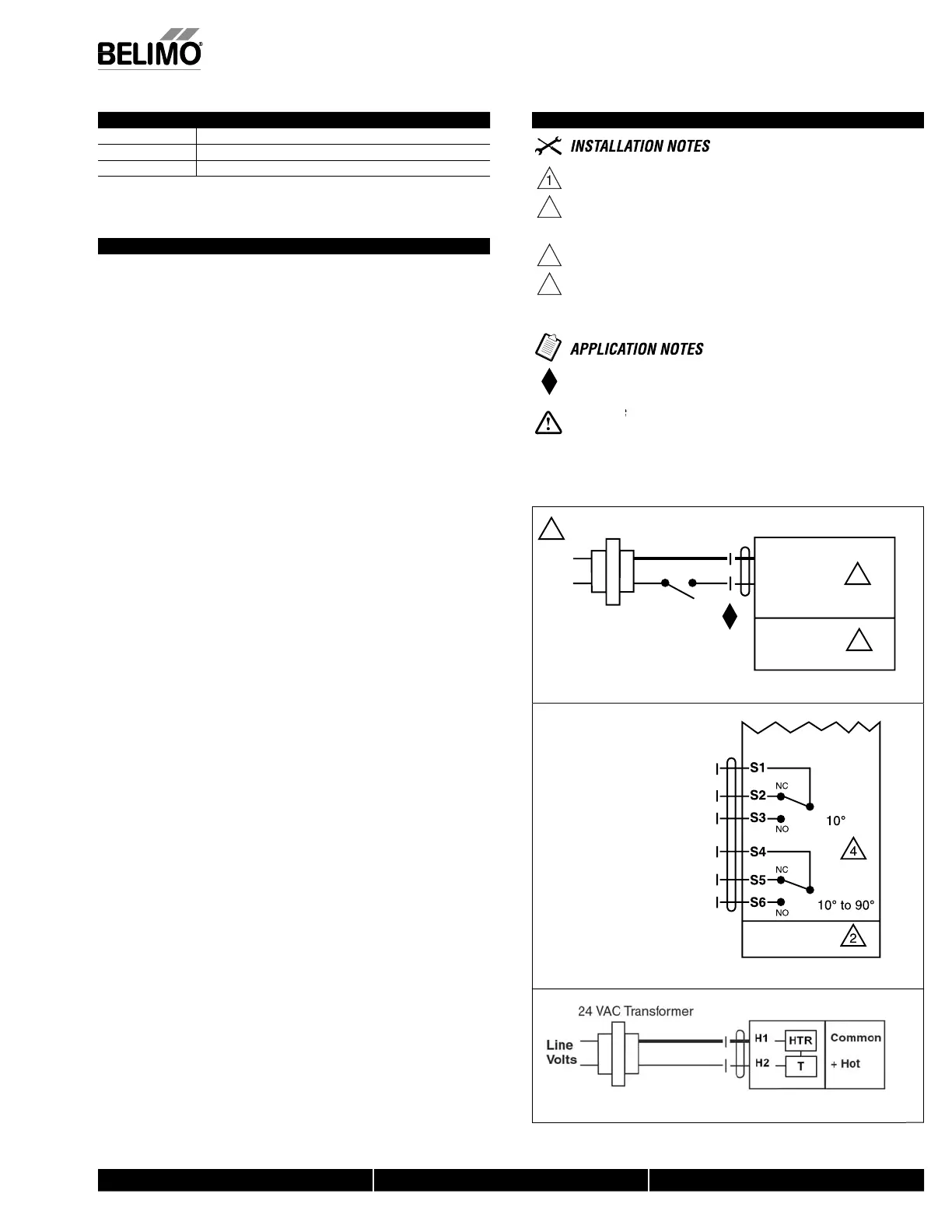
Wiring Diagrams
Provide overload protection and disconnect as required
A
TI
Equipment Damage!
Actuators may be connected in parallel
Power consum
tion and in
ut im
edance must be observed.
3
Actuators ma
also be
owered b
24 VDC.
For end
osition indication, interlock control, fan startu
, etc., AFB24-S
N4
H
, AFX24-
N4 incorporates two built-in auxiliary switches: 2 x
PDT,
A
0.5A
@250 VAC, UL Approved, one switch is fi xed at +10°, one is
a
usta
e 10° to 90°.
Meets cULus requirements without the need of an electrical ground
nn
ti
n
Live Electrical Components!
Durin
installation, testin
, servicin
and troubleshootin
o
this product, it may be
necessar
to work with live electrical com
onents. Have a
ualifi ed licensed electrician or other
individual who has been properly trained in handling live electrical components per
orm these
tasks. Failure to
ollow all electrical sa
et
recautions when ex
osed to live electrical com
o
nents cou
resu
t
n
eat
or ser
ous
n
ury
1 Common
2 + Hot
1
2
24 VAC Transformer
AFB24 N4(H)
AFB24-S N4(H)
AFX24 N4
AFX24-S N4
Line
Volts
3
W063
AFB
N4
On/Off wirin
AFB24-S N4(H)
AFX24-S N4
064
AFB24
-
N4
Auxiliary Switche
K-AF-NF N4H 24V heater
EMA 4 H
t
r
On/Off spring return damper actuators shall be direct coupled type which require
o crank arm and linka
e and be capable of direct mountin
to a
ackshaft up to a
1.05” diameter. The actuators must be designed so that they may be used for either
lockwise or counterclockwise fail-safe o
eration. Actuators shall be
rotected
from overload at all an
les of rotation. If required, two SPDT auxiliary switch shall
e provided having the capability of one being adjustable. Actuators with auxiliary
switches must be constructed to meet the re
uirements for Double Insulation so
an electrical ground is not required to meet agency listings. Actuators shall be
ULus A
roved and have a 5
ear warrant
, and be manufactured under ISO 9001
International
ualit
ontrol
tandards. Actuators shall be as manufactured b
Belimo
N40103 - 09/11 - Subject to change. © Belimo Aircontrols (USA), Inc.
 Loading...


