V3.3 07.2016•Subject to modifi cation
UL marked actuators is optional, please contact your local Sales Representative for details.
11
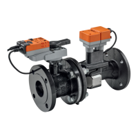
Functions when operated on MP-Bus
Connection on the MP-Bus Power topology
A) Additional actuators and
sensors (max. 8)
There are no restrictions for the
network topology (star, ring, tree
or mixed forms are permitted).
Supply and communication in the
same 3-wire cable
• no shielding or twisting required
• no terminating resister required
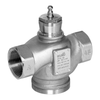
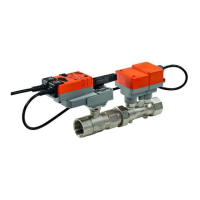
Connection of active sensors Connection of external switching contact
A) Additional actuators and
sensors (max. 8)
• Supply AC / DC 24V
• Output signal DC 0 ... 10V
(max. DC 0 ... 32V)
• Resolution 30mV
1 2 3 5
MP
p
+
–
U
Y
A)
A) Additional actuators and
sensors (max. 8)
• Switching current 16 mA @ 24V
• Start point of the operating
range must be parameterised on
the MP actuator as ≥ 0.6 V
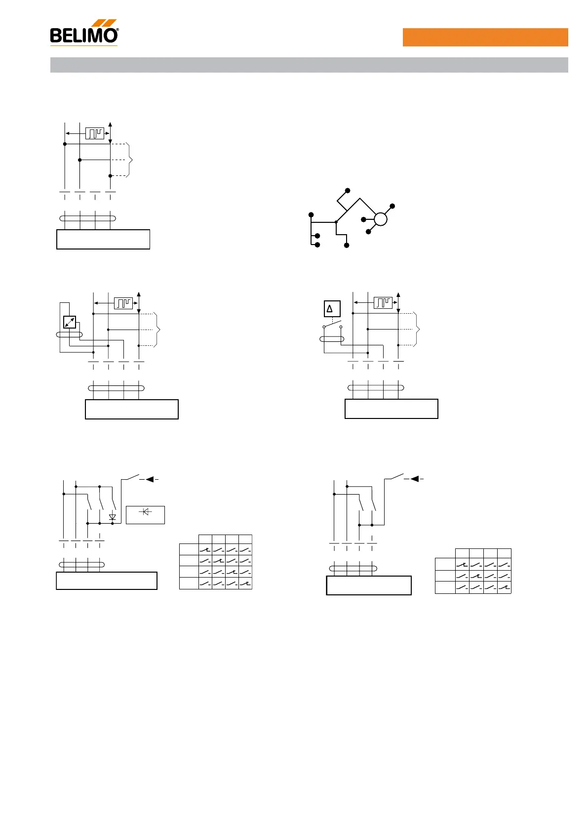
Functions for actuators with specific parameters
Override control and limitation with AC 24 V with
relay contacts
Override control and limitation with DC 24 V with
relay contacts
T
a b d
U
T
~
Y
e
5123
ab
Close
max
Open
Y
Y (DC 0 ... 10 V)
e.g. 1N 4007
ab
U
T
~
Y
e
5123
ab
Close
max
Y
Y (DC 0 ... 10 V)
1 2 3 5
MP
+
–
U
Y
A)
1 2 3 5
MP
+
–
U
Y
A)
EP..R+MP / P6..W..E-MP
Functions
 Loading...