EasyManua.ls Logo

Belimo EPF+MP Series - User Manual

Belimo EPF+MP Series
10 pages
Print Icon
To Next Page IconTo Next Page
Loading...
Technical data sheet EP..F+MP
Characterised control valve with
sensor-operated flow control, 2-way,
Flange, PN 16 (EPIV)
Nominal voltage AC/DC 24 V
Control modulating, communicative
For closed cold and warm water
systems
For modulating control of air-
handling and heating systems on the
water side
Communication via Belimo MP-Bus
or conventional control
Conversion of active sensor signals
and switching contacts
Type overview
Type DN
[ ]
DN
[“]
V’nom
[ l/s]
V’nom
[ l/min]
kvs theor.
[ m³/h]
PN
[ ]
n(gl)
[ ]
EP065F+MP 65 2 1/2 8 480
50
16 3.2
EP080F+MP 80 3 11 660
74
16 3.2
EP100F+MP 100 4 20 1200
126
16 3.2
EP125F+MP 125 5 31 1860
195
16 3.2
EP150F+MP 150 6 45 2700
254
16 3.2
kvs theor.: Theoretical kvs value for pressure drop calculation
Technical data
Electrical data Nominal voltage AC/DC 24 V
Nominal voltage frequency 50/60 Hz
Nominal voltage range AC 19.2...28.8 V / DC 21.6...28.8 V
Power consumption in operation 9.5 W
Power consumption in rest position 6.5 W
Power consumption for wire sizing 13 VA
Connection supply / control Cable 1 m, 4 x 0.75 mm²
Parallel operation Yes (note the performance data)
Functional data
Torque Motor 20 Nm (DN 65...80)
40 Nm (DN 100...150)
Operating range Y DC 2...10 V
Input Impedance 100 kΩ
Operating range Y variable Start point DC 0.5...24 V
End point DC 8.5...32 V
Options positioning signal Modulating (DC 0...32 V)
Position feedback U DC 2...10 V
Position feedback U note Max. 1 mA
Position feedback U variable Start point DC 0.5...8 V
End point DC 2...10 V
Sound power level Motor 45 dB(A)
Adjustable flow rate V’max 30...100% of Vnom
Control accuracy
±5% (of 25...100% Vnom) @ 20°C / Glycol 0%
vol.
Media
Cold and warm water, water with glycol up to
max. 60% vol.
Medium temperature -10...120°C
Close-off pressure ∆ps 690 kPa
Differential pressure ∆pmax 340 kPa
Flow characteristic equal percentage (VDI/VDE 2178), optimised in
the opening range (switchable to linear)
Leakage rate air-bubble tight, leakage rate A (EN 12266-1)
Pipe connectors Flange PN 16 according to EN 1092-2
Installation position upright to horizontal (in relation to the stem)
Servicing maintenance-free
Manual override with push-button, can be locked
www.belimo.com
EP..F+MP • en-ap • 2019-06-03 • subject to changes
1
Question and Answer IconNeed help?

Do you have a question about the Belimo EPF+MP Series and is the answer not in the manual?

Summary

Technical Specification Overview

Type overview

Provides a list of available valve types with specifications like DN, flow rates, and pressure ratings for selection.

Electrical data

Details electrical specifications including voltage, frequency, power consumption, and connection types for integration.

Functional data

Outlines functional parameters such as torque, operating ranges, input impedance, and feedback signals for operation.

Flow measurement

Explains the ultrasonic volumetric flow measurement principle, its accuracy, and minimum flow requirements.

Product Functionality and Features

Mode of operation

Describes the integrated system of valve, sensor, and actuator for controlling flow based on setpoints.

Control characteristics

Details how velocity is converted to flow rate and the relationship between control signals and valve position.

Overview

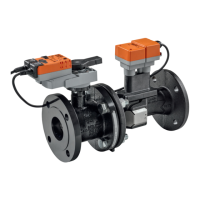
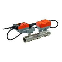
This document describes the Belimo EP..F+MP series of characterised control valves with sensor-operated flow control, designed for 2-way operation with flanges and PN 16 rating. These valves are suitable for closed cold and warm water systems, as well as for modulating control in air-handling and heating systems on the water side. They offer communicative control via Belimo MP-Bus or conventional control and can convert active sensor signals and switching contacts.

Function Description

The final controlling device consists of three main components: a characterised control valve (CCV), a measuring pipe with a volumetric flow sensor, and the actuator itself. The adjusted maximum flow (Vmax) is assigned to the maximum positioning signal (typically 10 V / 100%). The device can be controlled either communicatively or analogously. The medium's flow is detected by the sensor in the measuring pipe and used as the flow value. This measured value is then balanced with the setpoint, and the actuator adjusts the valve position to correct any deviation. The angle of rotation varies depending on the differential pressure across the final controlling element.

The velocity of the medium is measured by the sensor electronics and converted into a flow rate signal. The positioning signal Y corresponds to the power Q via the heat exchanger, and the volumetric flow is regulated within the EPIV. The control signal Y is converted into an equal-percentage characteristic curve, with the Vmax value serving as the new reference variable w. The momentary control deviation then forms the positioning signal Y1 for the actuator. Specially configured control parameters, combined with the precise flow rate sensor, ensure stable control quality, though they are not suitable for rapid control processes like domestic water control. U5 displays the measured volumetric flow as voltage (factory setting), or alternatively, it can show the valve opening angle, always in reference to the respective Vnom.

The flow direction, indicated by an arrow on the housing, must be observed to ensure correct flow rate measurement. To achieve specified measuring accuracy, a flow-calming or inflow section of at least 5x DN must be provided upstream from the flow sensor.

In cases of a flow sensor error, the EPIV will automatically switch from flow control to position control. Once the error is resolved, the EPIV reverts to its normal control setting.

Important Technical Specifications

Electrical Data:

  • Nominal Voltage: AC/DC 24 V
  • Nominal Voltage Frequency: 50/60 Hz
  • Nominal Voltage Range: AC 19.2...28.8 V / DC 21.6...28.8 V
  • Power Consumption (Operation): 9.5 W
  • Power Consumption (Rest Position): 6.5 W
  • Power Consumption (Wire Sizing): 13 VA
  • Connection Supply / Control: Cable 1 m, 4 x 0.75 mm²

Functional Data:

  • Torque Motor: 20 Nm (DN 65...80), 40 Nm (DN 100...150)
  • Operating Range Y: DC 2...10 V
  • Input Impedance: 100 kΩ
  • Operating Range Y Variable: Start point DC 0.5...24 V, End point DC 8.5...32 V
  • Position Feedback U: DC 2...10 V (Max. 1 mA)
  • Sound Power Level (Motor): 45 dB(A)
  • Adjustable Flow Rate V'max: 30...100% of Vnom
  • Control Accuracy: ±5% (of 25...100% Vnom) @ 20°C / Glycol 0% vol.
  • Media Temperature: -10...120°C
  • Close-off Pressure Aps: 690 kPa
  • Differential Pressure Apmax: 340 kPa
  • Flow Characteristic: Equal percentage (VDI/VDE 2178), optimised in the opening range (switchable to linear)
  • Leakage Rate: Air-bubble tight, leakage rate A (EN 12266-1)
  • Pipe Connectors: Flange PN 16 according to EN 1092-2

Flow Measurement:

  • Measuring Principle: Ultrasonic volumetric flow measurement
  • Measuring Accuracy Flow: ±2% (of 25...100% Vnom) @ 20°C / Glycol 0% vol.
  • Min. Flow Measurement: 1% of Vnom

Safety:

  • Protection Class IEC/EN: III Safety Extra-Low Voltage (SELV)
  • Degree of Protection IEC/EN: IP54
  • EMC: CE according to 2014/30/EU
  • Ambient Temperature: -30...50°C
  • Storage Temperature: -20...80°C
  • Ambient Humidity: Max. 95% r.H., non-condensing

Materials:

  • Flow Measuring Pipe: EN-GJL-250 (GG 25), with protective paint
  • Closing Element: Stainless steel AISI 316
  • Stem Seal: EPDM
  • Ball Seat: PTFE, O-ring Viton

Usage Features

Installation:

  • Recommended Installation Positions: The ball valve can be installed upright to horizontal. It should not be installed in a hanging position (stem pointing downwards). Installation in the return line is recommended.
  • Water Quality Requirements: Adherence to VDI 2035 water quality requirements is essential. The water must have a conductivity ≥ 20 µS/cm for correct functioning. Strainers are recommended to prevent particle debris from interfering with valve operation.
  • Stem Heating: For cold water applications and warm, humid ambient air, stem heating can be enabled to prevent condensation and corrosion in the actuator gearbox. This feature should only be active when the system is in operation as it lacks temperature control.

Control and Configuration:

  • Creep Flow Suppression: At very low flow speeds, the sensor may not measure within tolerance. This range is electronically overridden.
  • Opening/Closing Valve: The valve remains closed until the volumetric flow required by the positioning signal Y corresponds to 1% of Vnom. Control along the characteristic curve is active above this value. When the flow rate falls below 1% of Vnom, it is maintained at 1%. If it falls below 0.5% of Vnom, the valve closes.
  • Converter for Sensors: The MP actuator allows connection of an active sensor or switching contact, acting as an analogue/digital converter to transmit the sensor signal via MP-Bus to the higher-level system.
  • Configurable Actuators: Factory settings cover common applications, but parameters can be modified using Belimo Service Tools MFT-P or ZTH AP.
  • Positioning Signal Inversion: The analogue positioning signal can be inverted, reversing standard behavior (0% signal for Vmax, 100% for closed).
  • Hydraulic Balancing: Using Belimo tools, the maximum flow rate can be adjusted on-site. If integrated into a management system, balancing can be handled directly by the system.
  • Manual Override: A push-button allows manual override; the gear disengages while pressed or locked.

Operating Controls and Indicators:

  • Push-button and LED Display (Green): Indicates power supply/malfunction (off), in operation (on), or triggers angle of rotation adaptation (press button).
  • Push-button and LED Display (Yellow): Indicates standard mode without MP bus (off), MP communication active (flickering), adaptation/synchronisation active (on), or confirms addressing (press button).
  • Gear Disengagement Button: Disengages gear (press) for manual override; engages gear (release) to start synchronisation.
  • Service Plug: For connecting parameterisation and service tools.
  • Power Supply Check: If green LED is off and yellow LED is on, a wiring error is possible.

Maintenance Features

  • Maintenance-Free: Ball valves, rotary actuators, and sensors are designed to be maintenance-free.
  • High Functional Reliability: The actuator is overload protected, requires no limit switches, and automatically stops when the end stop is reached.
  • Servicing Precautions: Before any service work, the rotary actuator must be isolated from the power supply. Any pumps in the relevant piping system must be switched off, and appropriate slide valves closed. Components should be allowed to cool, and system pressure reduced to ambient level.
  • Reassembly: The system must not be returned to service until the ball valve and rotary actuator are correctly reassembled according to instructions, and the pipeline refilled by professionally trained personnel.

Belimo EPF+MP Series Specifications

General IconGeneral
BrandBelimo
ModelEPF+MP Series
CategoryControl Unit
LanguageEnglish

Related product manuals