ENG-93001-93227-01.00 • ZSD • Subject to technical changes
L
0
.2
.4
.6
.8
1
R
0
.2
.4
.6
.8
1
T
~
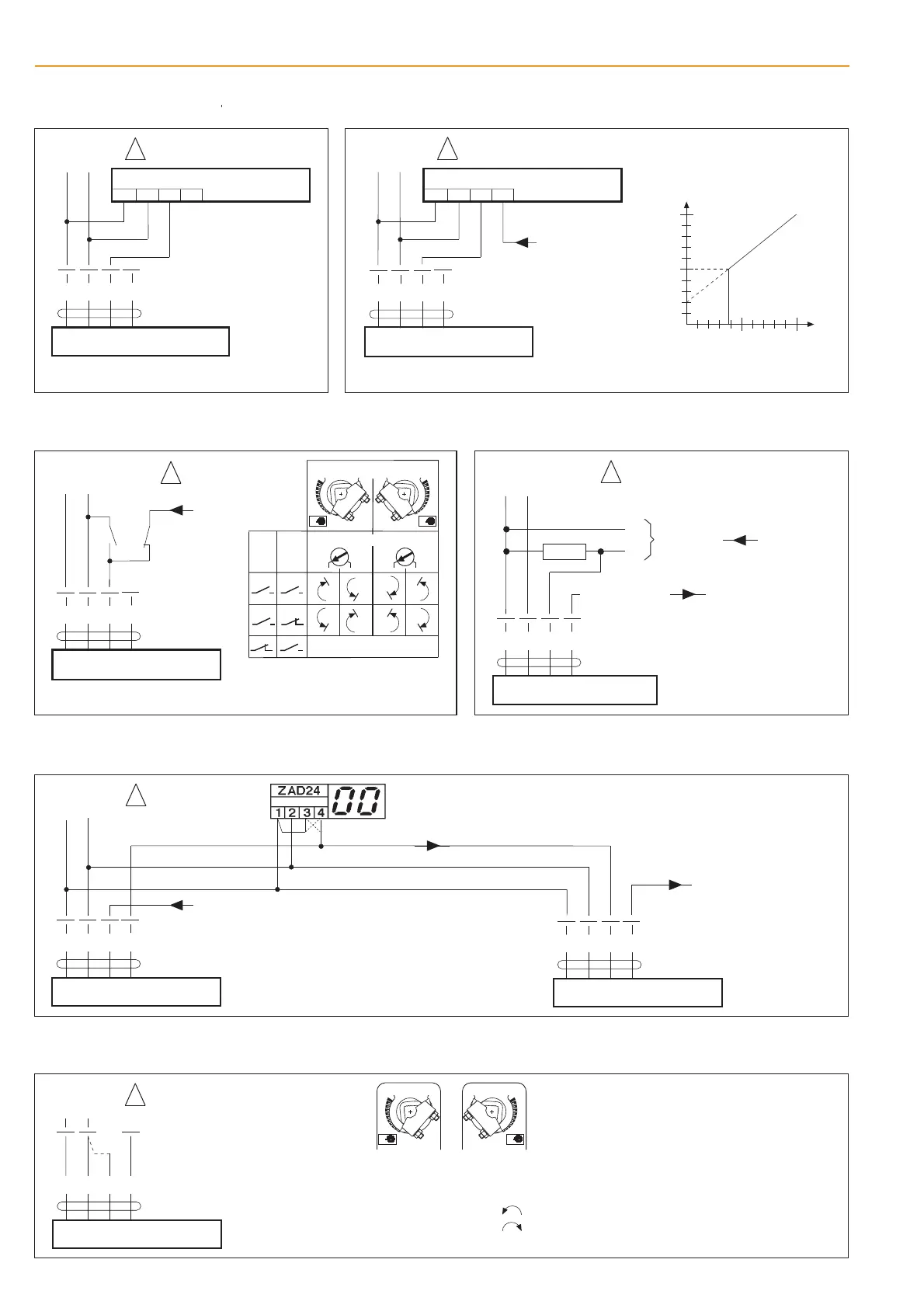
Function monitoring
AC 24 V
123
T
~
Remote control 0...100%
123
SGA24, SGF24
SGE24
Positioner
4
Y
T
~
Z
LF24-SR
Parallel connection of further
actuators is possible (up to 10).
T
~
123
SGA24, SGF24
SGE24
Positioner
4
Y
T
~
Z
Parallel connection of further
actuators is possible (up to 10).
Minimum position
Y DC 0...10 V
(from controller)
100%
Angle of rotation
0%
Y [ V ]
10 V
min.
0 V
AC 24 V
AC 24 V
Connect via safety
isolating transformer
!
Connect via safety
isolating transformer
!
Connect via safety
isolating transformer
!
Y
U
T
~
-
+
5
123
5
LF24-SR
Y
U
T
~
-
+
Control by 4...20 mA via external resistor
Procedure
• AC 24 V at terminals 1 and 2
• Disconnect terminal 3:
– For direction of rotation "L": actuator runs
– For direction of rotation "R": actuator runs
• link terminals 2 and 3: actuator runs in the opposite direction
LF24-SR
Y
U
T
~
-
+
123
5
T
~
Position indication and / or master-slave control (depending on position)
AC 24 V
Position indication
LF24-SR
to next actuator
Slave actuator
Connect via
safety isolating
transformer
!
Y
U
T
~
-
+
123
5
Note ± 5%
synchronism tolerance
between actuators
Master-slave control
LF24-SR
Master actuator
Y
U
T
~
-
+
123
5
Override control
LF24-SR
Parallel connection of several actuators is
possible. Power consumption must be observed.
a
b
4...20 mA
U DC 2...10 V
Y
123
LF24-SR
5
U
T
AC 24 V
-
+
DC 24 V
T
~
-
+
Connect via
safety isolating
transformer
~
(-)
(+)
500 1
*
*
The 500 1 resistor converts the
4...20 mA current signal to a
voltage signal of DC 2...10 V.
!
T
AC 24 V
-
+
DC 24 V
~
Connect via
safety isolating
transformer
!
Y
U
T
~
-
+
123
5
L
0
.2
.4
.6
.8
1
R
0
.2
.4
.6
.8
1
a
b
Control mode
R
L
R
L
Reversing switch
Mounting side
Y DC 0...10 V
Y DC 0...10 V
10
Control and monitoring functions LF24-SR
w0116712
BC

 Loading...