1
0
.2
.4
.6
.8
S1
S2
S3
S1
S2
S3
0
.2
.4
.6
.8
1
R
1
S1
S1
S2
S3
S2
S3
0
.2
.4
.6
.8
0
.2
.4
.6
.8
1
L
ENG-93001-93227-01.00 • ZSD • Subject to technical changes
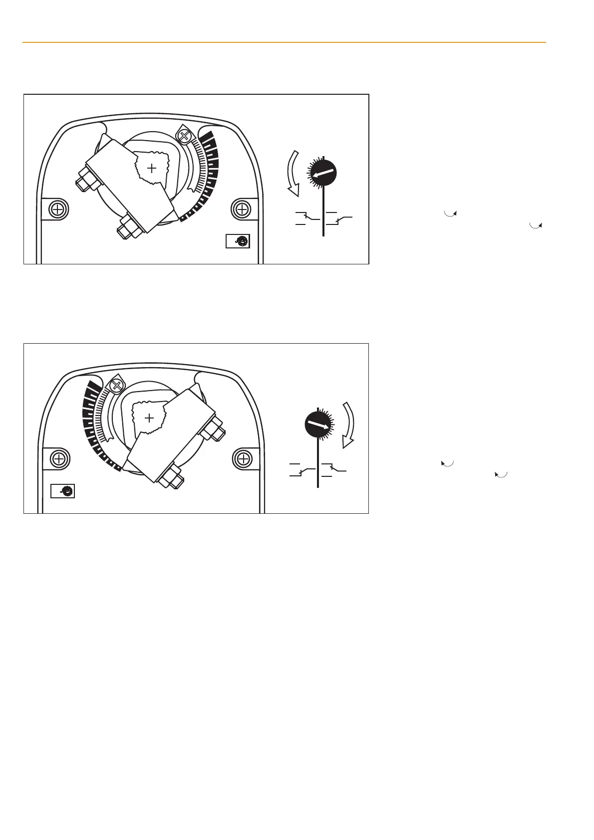
Starting point:
Actuator in safe position
Procedure
– Turn the knob of the auxiliary switch un-
til the tip of the arrow is pointing to the
required switching position (see left).
Example: Switching point setting = .4
corresponds to 40% angle of rotation.
– When the actuator runs to the operating
position (ccw ), the switch knob will
also rotate counter-clockwise (ccw )
and the auxiliary switch will operate as
the tip of the arrow passes the scale
zero (S1–S3 linked).
Starting point:
Actuator in safe position
Procedure
– Turn the knob of the auxiliary switch un-
til the tip of the arrow is pointing to the
required switching position (see left).
Example: Switching point setting = .4
corresponds to 40% angle of rotation.
– When the actuator runs to the operating
position (cw ), the switch knob will
also rotate clockwise (cw ) and the
auxiliary switch will operate as the tip of
the arrow passes the scale zero (S1–S3
linked).
6
Adjusting the auxiliary switch LF24-S, LF230-S
Mounting side R
Mounting side L
m0037712
m0038712
BC

 Loading...