3
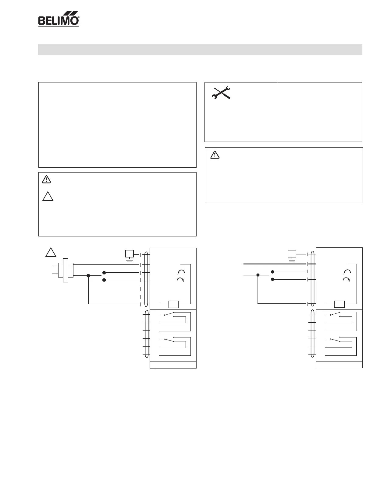
Wiring
On/Off, 24V, 120/230V
SY Actuator Wiring Diagram, SY1…5-24 – On/Off
SY1…12-110 (220) On/Off
Observe class 1 and class 2 wiring restrictions.
Transformer sizing = SY actuator draw X 1.25 (safety margin)
(Ex. SY2-24 requires 3.0A x 1.25 = 3.75A,
3.75A X 24 VAC = 90VA Transformer).
Indicates an action or condition that may cause irreversible
damage to the actuator(s) or associated equipment.
Equipment damage!
Power consumption and input impedance must be observed.
CAUTION
Indicates a potentially hazardous situation which, if not avoided,
may result in minor or moderate injury. It may also be used to
alert against unsafe practices.
Warnings and Cautions appear at appropriate sections throughout
this manual. Read these carefully.
Hazard Identification
INSTALLATION NOTES
NOTES SY1…5-24
Each actuator should be powered by a single, isolated
control transformer.
• Isolation relays must be used in parallel connection of multiple actuators
using a common control signal input.
• "H" cannot be connected to terminal #3 and #4 simultaneously.
• Required: Terminal #7 needs to be field wired to enable heater circuit.
24 VAC Transformer
Line
Volts
Open
Close
G Ground
1 Common
3 Open
4 Closed
5
Connect to #1 for fully
open indication
6
Connect to #1 for fully
closed indication
7
G Ground
1 Common
3 Open
4 Closed
5
Connect to #1 for fully
open indication
6
Connect to #1 for fully
closed indication
7
HTR
A
B
C
D
E
F
LS3
A-C
(Open Indication)
LS4
D-F
(Closed Indication)
Contact Rating: 5A 250 VAC Max.
SY2…5-24
120 and 230 VAC
G
Open
Close
G
N L1
H L2
HTR
A
B
C
D
E
F
LS3
A-C
(Open Indication)
LS4
D-F
(Closed Indication)
Contact Rating: 5A 250 VAC Max.
SY2…12-110 (220)
NOTES SY1…12-110 (220)
• Caution: Power Supply Voltage
• Isolation relays must be used in parallel connection of multiple actuators
using a common control signal input.
• "H" (L2) cannot be connected to terminal #3 and #4 simultaneously.
• Required: Terminal #7 needs to be field wired to enable heater circuit.
SY1-24
A
B
C
E
F
Contact Rating: 5A 125 VAC Max.
3A 250 VAC Max.
A-B (Open Indication)
LS4
LS3
A-E (Closed Indication)
SY1-110 (220)
A
B
C
E
F
Contact Rating: 5A 125 VAC Max.
3A 250 VAC Max.
A-B (Open Indication)
LS4
LS3
A-E (Closed Indication)
SY1 Contact Arrangements
33
33
W546
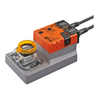
Actuators: SY4...12-110 SY4...12-220
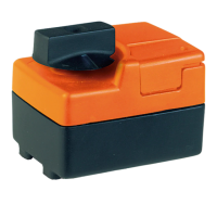
SY4...5-24
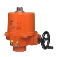
SY4...12-110 (220)
SY4...5-24
SY4...12-110 (220)
71906-00001 Subject to change. © Belimo Aircontrols (USA), Inc.
 Loading...