11
I20683 - Subject to change.
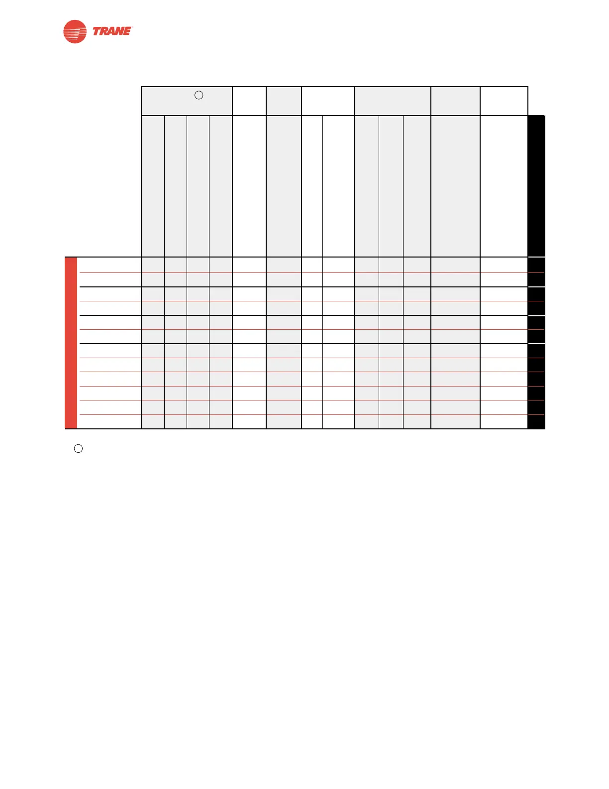
Non-Spring Return Actuator Product Range
Actuator Application Chart
Torque Running Power Power Control Position Auxiliary
Time Supply Consumption Input Feedback Switches
(based on 4 in-lb per sq. ft)
TGMB24-3† ● 150 ● 7 4.5 (2) ●● ● 76
TGMB24-SR† ● 150 ● 7 4.5 (2) ●● ●78
TAMB24-3 ● 95 ● 6 2.5 (0.5) ●● ● 82
TAMB24-SR ● 95 ● 5 2.5 (0.5) ●● ●84
TNMB24-3 ● 95 ● 4 2.5 (0.5) ●● ● 88
TNMB24-SR ● 95 ● 4 2.5 (0.5) ●● ●90
TLMB24-3 ● 95 ● 2 1.5 (0.2) ●● ● 94
TLMB24-3-T ● 95 ● 2 1.5 (0.2) ●● ● 94
TLMB24-3-T.1 ● 95 ● 2 1.5 (0.2) ●● ● 94
TLMB24-SR ● 95 ● 3 1.5 (0.5) ●● ●96
TLMB24-SR-T ● 95 ● 3 1.5 (0.5) ●●96
TLMB24-SR-T.1 ● 95 ● 3 1.5 (0.5) ●●96
†For dual mounting on a single shaft the total sizing torque must not exceed 640 in-lbs (-3 and -SR wired in parallel).
For complete guide to sizing actuators see page 5.
45 in-lb [5 Nm], Apprx. 11 sq. ft.
90 in-lb [10 Nm], Apprx. 22 sq. ft.
180 in-lb [20 Nm], Apprx. 45 sq. ft.
360 in-lb [40 Nm], Apprx. 90 sq. ft.
Motor Drive
24 VAC +/- 20%, VDC +/- 15%
VA Rating
Wattage Running (holding)
On/Off
Floating Point
2-10 VDC
4-20 mA (w/500Ω resistor)
2-10 VDC
Add-on
See Page Number
Non-Spring Return
Airside Products
B
B