24
I20683 - Subject to change.
Installation Instructions
Electrical Operation
General
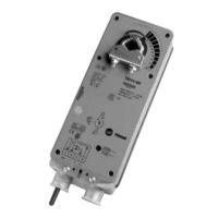
The TAF series actuators utilize brushless DC motor technolo-
gy. The TAF uses this motor in conjunction with an Application
Specific Integrated Circuit (ASIC). In the On-Off versions of
the TAF, the ASIC monitors and controls the actuator’s rota-
tion and a digital rotation sensing function to prevent damage
to the actuator. The TAF24… modulating type actuators incor-
porate a built in microprocessor. The microprocessor provides
the intelligence to the ASIC to provide a constant rotation rate
and knows the actuator’s exact zero position.
Brushless DC Motor Operation
A brushless DC motor spins by reversing the poles of
stationary electromagnets housed inside of a rotating
permanent magnet. The electromagnetic poles are switched
by a special ASIC circuit. Unlike the conventional DC motor,
there are no brushes to wear or commutators to foul.
Overload Protection
The TAF series actuators are protected from overload at all
angles of rotation. The ASIC circuit constantly monitors the
rotation of the DC motor inside the actuator and stops the
pulses to the motor when it senses a stall condition. The DC
motor remains energized and produces full rated torque to the
load. This helps ensure that dampers are fully closed and that
edge and blade seals are always properly compressed.
Motor Position Detection
The brushless DC motors eliminate the need for potentiome-
ters for positioning in modulating type actuators. Inside the
motor are three “Hall Effect” sensors. These sensors detect
the spinning rotor and send pulses to the microprocessor
which counts the pulses and calculates the position to within
1/3 of a revolution of the motor.
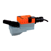
TAF24-SR actuators have built-in brushless DC motors which provide better accuracy and longer service life.
The TAF24-SR actuators are designed with a unique non-symmetrical deadband. The actuator follows an increasing or
decreasing control signal with a 80 mV resolution. If the signal changes in the opposite direction, the actuator will not respond
until the control signal changes by 200 mV. This allows these actuators to track even the slightest deviation very accurately,
yet allowing the actuator to “wait” for a much larger change in control signal due to control signal instability.
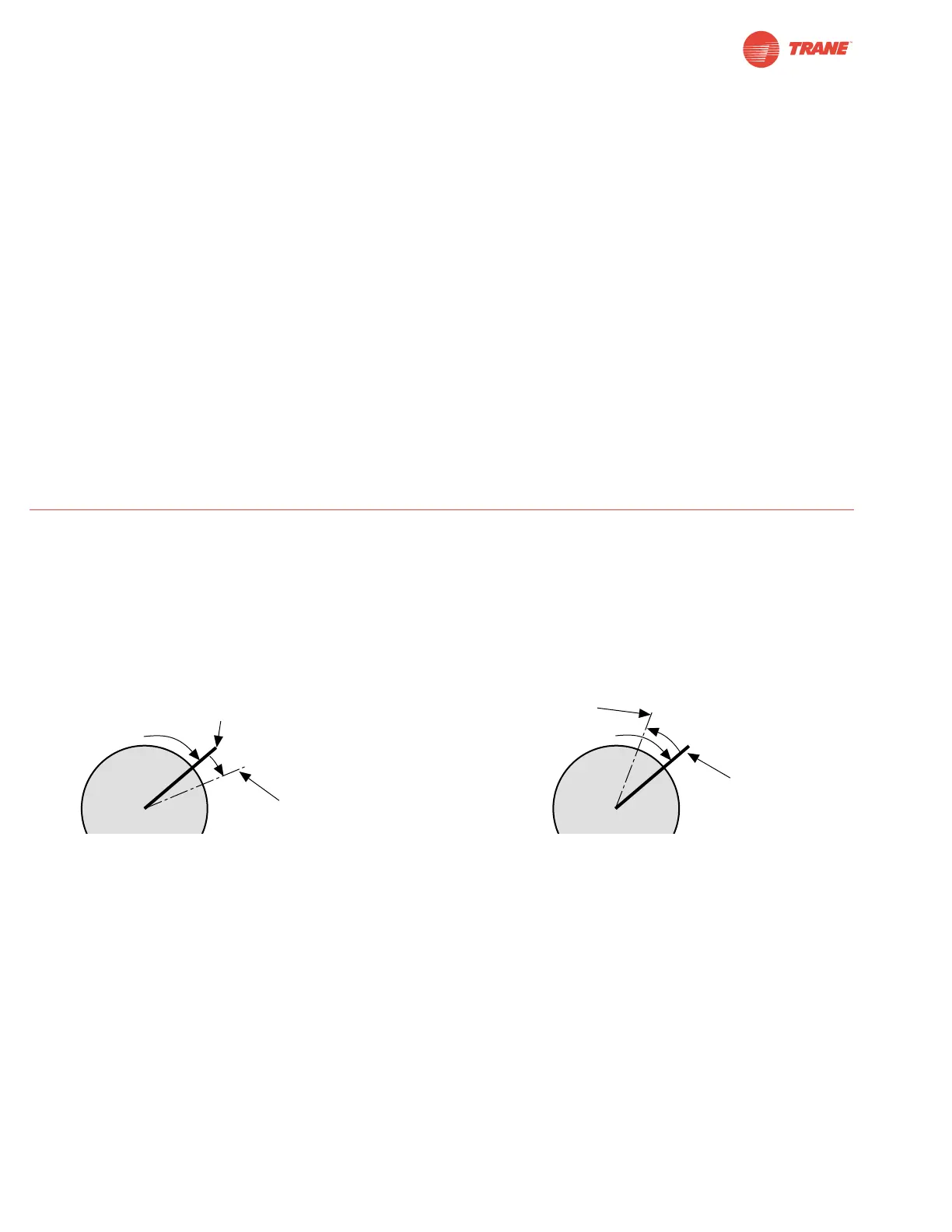
Control Accuracy and Stability
 Loading...