5902 Bell 202 Modem Hardware Manual
October 19, 2007
4 Installation
The installation of the 5902 modem requires mounting the modem on the 7.5mm by 35mm DIN rail
and connecting the 5902 modem to the system I/O Bus. Refer to the System Configuration Guide,
at the beginning of this manual, for complete information on system layout, I/O Bus cable routing
and 5902 modem installation.
4.1 Connecting the Modem
The 5902 modem is normally connected to the SCADAPack I/O Bus through the I/O Bus
Connectors as shown in figure 1.In this configuration the SCADAPack provides a modem reset
(/RST) signal and a signal to enable the leds (LEDON) on the 5902 modem.
The 5902 modem is also available in a stand alone (SA) configuration. In this configuration the
5902 is not connected to a SCADAPack controller and the modem reset (/RST) signal and a signal
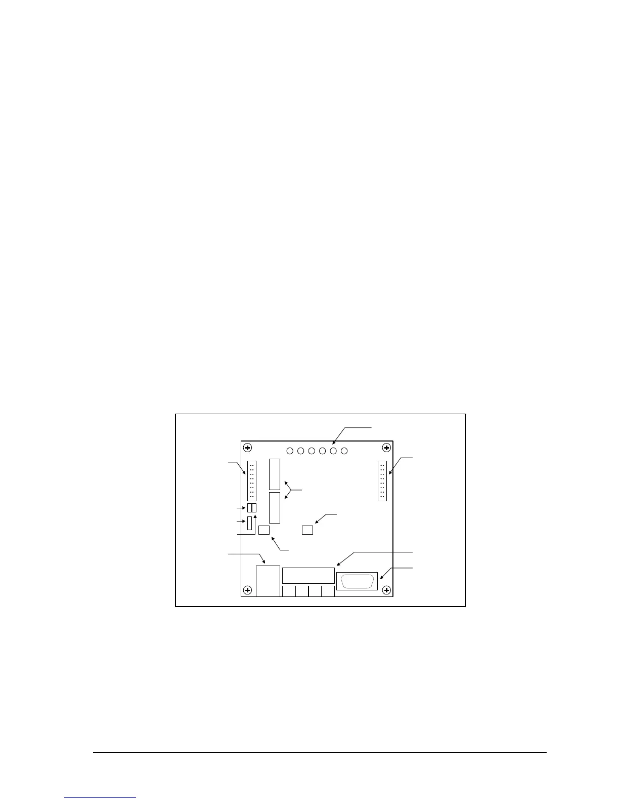
to enable the leds (LEDON) on the 5902 modem are not available. Two jumpers, J1 and J2, are
included to enable these signals on the 5902SA modem. Figure 1: 5902 Module Layout shows the
location of the jumpers.
5902 Modem
Remove jumper at J1 (/RST).
Remove jumper at J2 (LEDON).
5902SA Modem
Install jumper at J1 (/RST).
Install jumper at J2 (LEDON).
Figure 1: 5902 Module Layout