5902 Bell 202 Modem Hardware Manual
October 19, 2007
5.3 Sample Configurations
This section describes sample configurations for most situations. If the sample configurations do not
work with your system check section 5.5-Common Problems and Solutions or use the general
configuration procedures in section 5.4-System Configuration Procedures.
Refer to sections 4.3-Connecting to Dedicated Lines and 4.4-Connecting to a Radio sections for
wiring details.
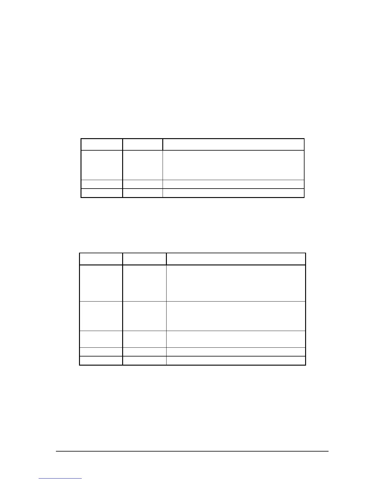
5.3.1 Full Duplex Back-to-Back Modems
Use this configuration to connect two modems over a four wire network. Switches not shown in the
table below are either ignored or are not critical.
Adjust these switches for a longer delay, to pause
before each transmission. The DTE must be
configured for half duplex with RTS/CTS
handshaking to use this feature.
Full duplex must be selected.
Close switch to engage loop back test.
5.3.2 Full Duplex Constant Carrier Master
Use this configuration for a master modem connected to one or more slave modems on a multi-
dropped, four wire network. This configuration is essentially a full duplex modem, except that the
carrier detect and carrier loss delays need adjustment since the slave transmitters are turning on and
off. Switches not shown in the table below are either ignored or are not critical.
The RTS/CTS delay creates a pause before each
transmission. Adjust these switches to lengthen
the delay. The DTE must implement proper half
duplex, RTS/CTS handshaking to use this
feature.
Adjust these switches for a longer delay, to
reduce noise at the beginning of each reception.
Ensure that the RTS/CTS delay on slave
modems is longer than this delay.
Adjust these switches to add carrier loss delay as
required.
Full duplex must be selected.
Close switch to engage Loop Back test.