5902 Bell 202 Modem Hardware Manual
October 19, 2007
4.2 Field Wiring
The 5902 modem has three connectors for field wiring.
The RS-232 port is wired to the DE-9S socket connector. Refer to section 4.2.1-RS-232 Serial Port
for more information.
The modem wiring is terminated on either an 8 pole terminal block or an RJ-45 modular jack. The
terminal block is used for radios, private lines and leased telephone lines. The jack is used typically
for telephone lines. Refer to section 4.2.2-Terminal Block and 4.2.3-RJ-45 Modular Jack for more
information.
The modem operates on radios, two wire networks, four wire multi-point networks, and four wire
point-to-point networks. Section 4.3-Connecting to Dedicated Lines describes wiring networks on
dedicated lines. Section 4.4-Connecting to a Radio describes wiring to radios.
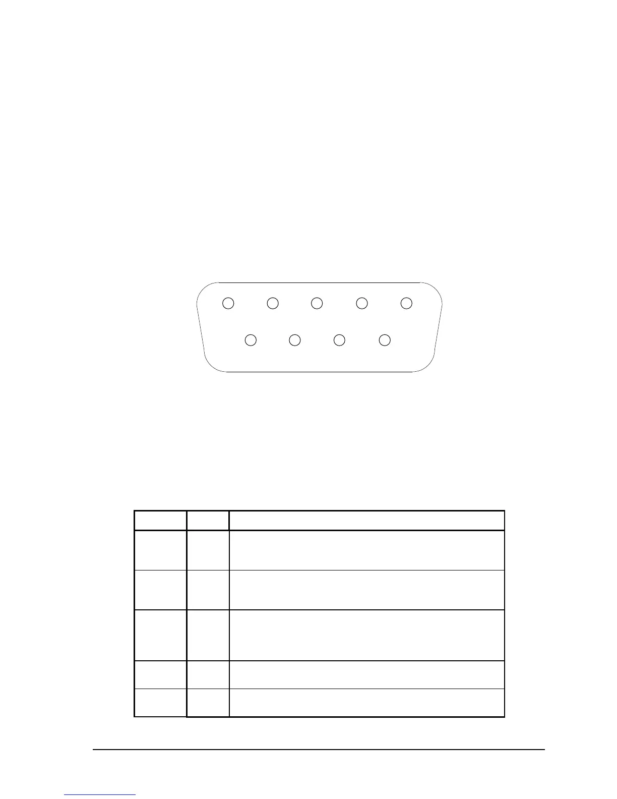
4.2.1 RS-232 Serial Port
Figure 2: RS-232 Port Connector (DCE)
The RS-232 port is a 9-pin female D-sub-miniature connector (DE-9S) configured as Data
Communications Equipment (DCE). A maximum cable length of 50 feet (15.2 m) is allowed. Figure
2: RS-232 Port Connector (DCE) and the table below describe the RS-232 connector.
In the following table a MARK is a voltage of +3 volts or greater; a SPACE is a voltage of –3 volts
or less.
This signal is at a MARK level when carrier is detected by
the modem on the receiver inputs.
The CD led is on for a MARK level.
Data received by the modem is output on this pin. The level
is SPACE on standby and MARK for received data.
The RD LED is lit for a MARK level.
Data transmitted by the modem is input on this pin from the
DTE. The level is SPACE on standby and MARK for
transmitted data.
The TD LED is lit for a MARK level.
This signal indicates that the DTE is ready to receive data.
It is not used by the modem.
This pin is connected to the I/O system ground.