22
ADJUSTMENT
WARNING
Engine should be o before adjusting any controls.
Extreme caution should be used when operating tiller in the reverse direction.
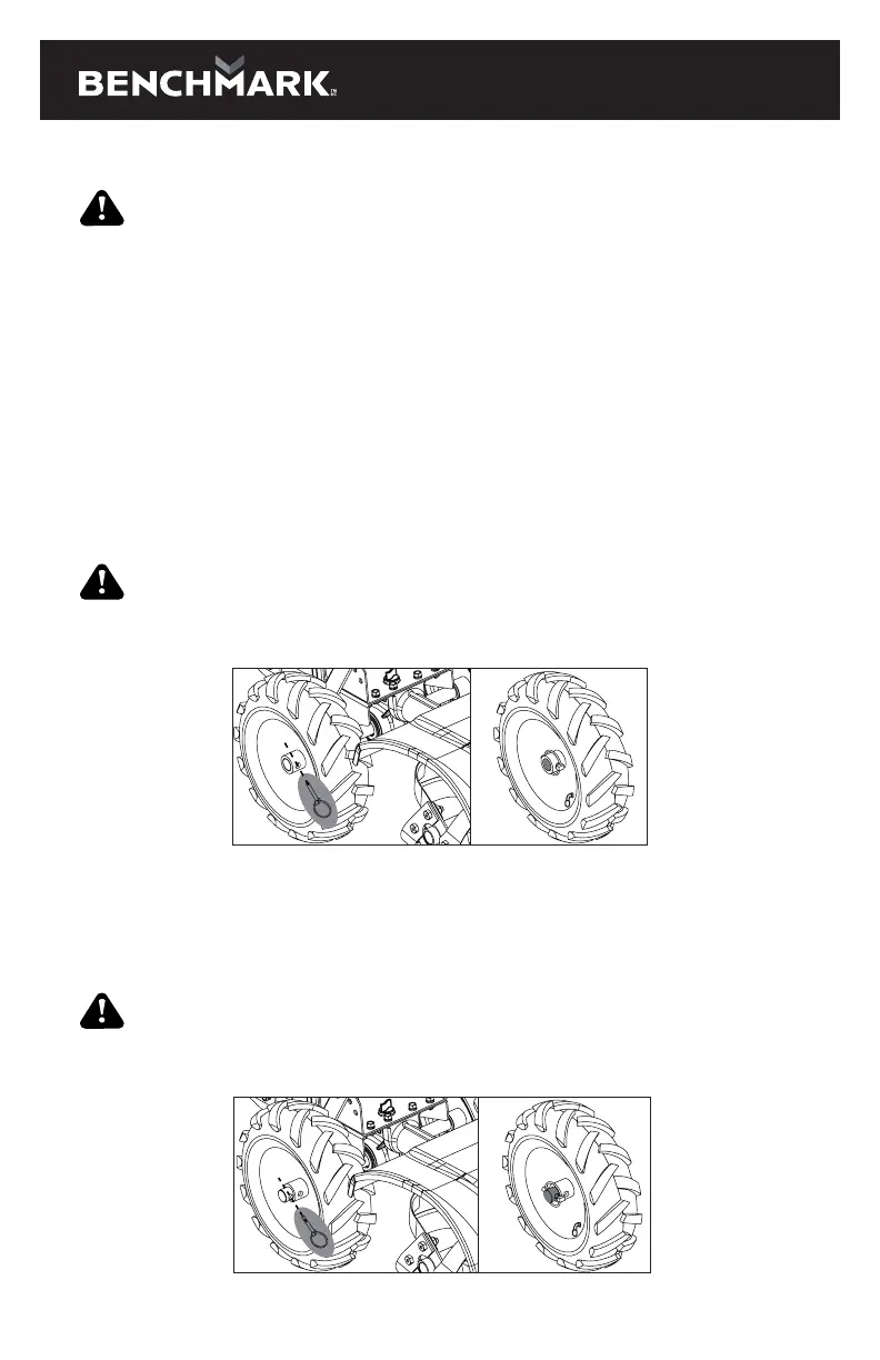
WHEEL LOCK PINS
Place wheels in tilling position.
1. Remove lock pin. Align hole in axle with hole in wheel hub.
2. Insert lock pin through holes of axle and wheel hub, fold lock pin ring to secure
pin to axle.
3. Firmly lock wheel and axle together before tilling.
4. Repeat for other wheel.
WARNING
Always have both wheel lock pins in to place the wheels in the tilling position. Do not
operate tiller with only one wheel locked.
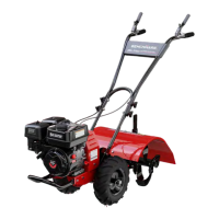
Place wheels in free-wheel position.
1. Remove lock pin. Slide wheel inward toward machine.
2. Insert pin in axle only, fold lock pin ring to secure pin to axle.
3. Wheel should turn freely on axle.
WARNING
Always have both wheel lock pins in to place the wheels in the free-wheel position
for transport.