DAC1 USB
Instruction Manual Revision D Page 9
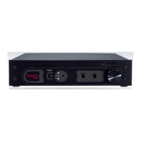
Front Panel
Input Status Display
The DAC1 USB has three LED’s on the front
panel that indicate which digital input is
selected. These LED’s flash when an error
condition occurs. All LED’s turn off when the
DAC1 USB is in Standby Mode.
Input Selector Switch
The input selector toggle switch is located
directly to the right of the Input Status
Display.
The switch is a momentary 3-position switch
that scrolls up and down through the 4 digital
inputs in a round-robin format.
If the DAC1 USB is in Standby Mode it will
resume normal operation when the Input
Selector Switch is toggled.
Input Indication
The numbers to the left of the LED’s
correspond to the following inputs:
1. Coaxial (bottom LED)
2. XLR (middle LED)
3. Optical (top LED)
4. USB (top and bottom LED’s)
When the top and bottom LED’s are lit
simultaneously, the USB (Input 4) is selected.
Error Indication
The Input Status Display will flash when an
error occurs on the selected digital input. The
number of times the display flashes before
entering standby indicates the type of error.
If the error is not resolved within about 15
seconds, the DAC1 USB will enter Standby
Mode. The DAC1 USB will resume normal
operation when it detects a valid input signal
at the last chosen input.
Error Codes:
• No signal – 16 slow flashes – audio
muted
• Data transmission errors - 16 flashes –
audio muted
• Non-PCM – 16 flashes – audio muted
• Non-audio – 32 rapid flashes – audio
muted
• Invalid sample (v-bit) – 64 very rapid
flashes – no mute
Common causes of errors are:
• Disconnected cable
• Data drop-outs due to a bad cable
• Incompatible audio data type (AC3,
ADAT, etc.)
• Non-Audio data