Benchmark Media Systems, Inc.
Page 15 of 39
JUMPER SETTINGS:
Jumpers are provided for special applications. A 2-pin jumper plug at header P2 can be moved in order to disable
the front-panel input selection switch. A jumper at JP7 can be removed to disable the 75-Ω termination on the
coaxial digital input. Four 8-pin headers (P5, P6, P7, and P8) allow selection of the output level at the XLR jacks.
Caution: Do not change any jumpers other than P2, P5, P6, P7, P8, and JP7. All other jumpers are for test
purposes only. Jumpers must always be installed at JP1, JP2, JP5, and JP6 (power supply enable jumpers).
Jumpers should not be installed on header P9.
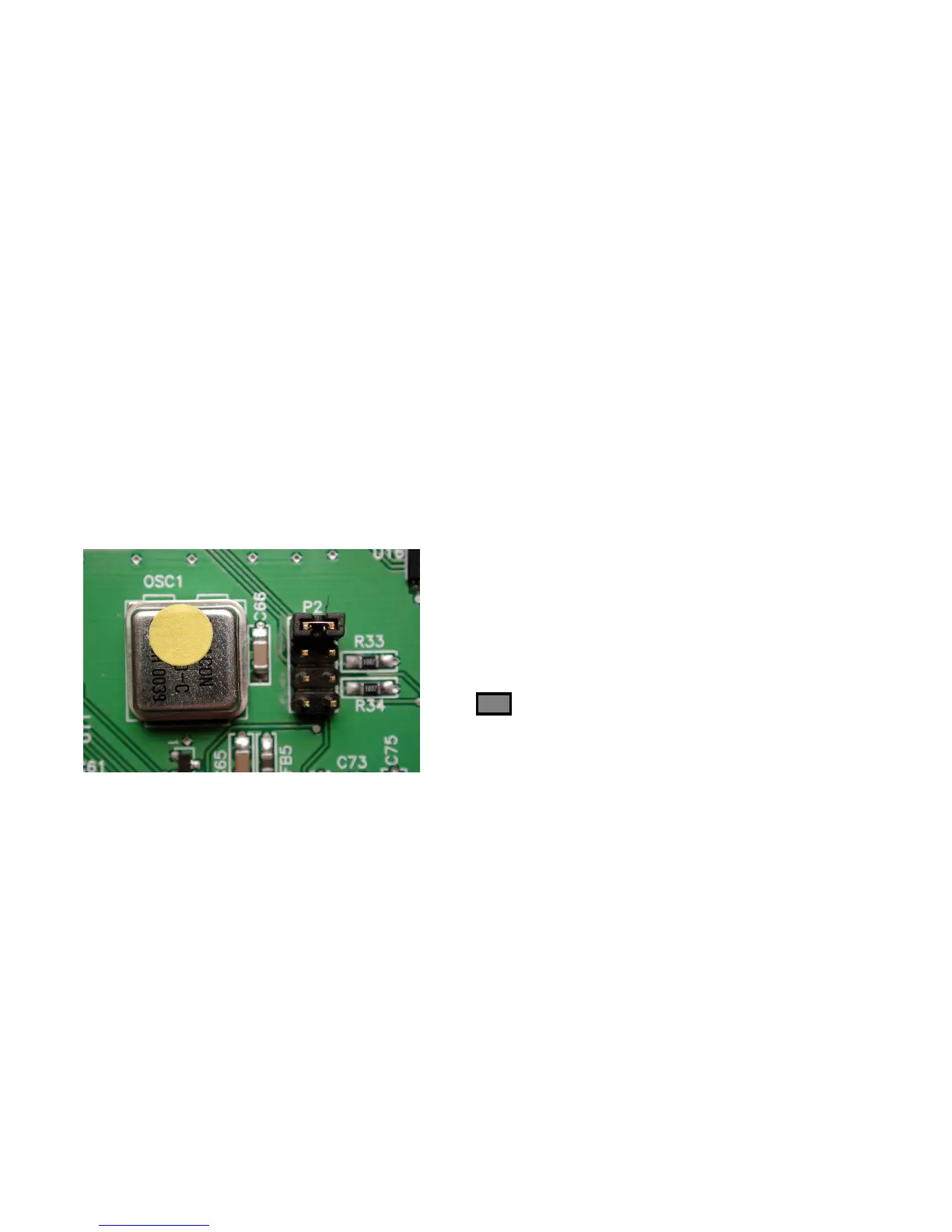
Input Source Select Jumper (P2):
A 2-pin jumper on header P2 (see Photo 1) can be used to disable the front-panel source-selection switch. This
feature is useful when the DAC1 is in a critical audio path, and only one of the three digital inputs will be used. In
such an application, the digital source selection can be made using the jumper on header P2. This can prevent
loss of audio due to operator error. The 2-pin jumper allows selection of:
•
Switchable Input *** (digital input selection using front-panel switch) – (Jumper plug between pins 1 and 2 of
the header)
•
Optical Input Only (front-panel switch is disabled) – (Jumper plug between pins 3 and 4 of the header)
•
Coaxial Input Only (front-panel switch is disabled) – (Jumper plug between pins 5 and 6 of the header)
•
XLR Input Only (front-panel switch is disabled) – (Jumper plug between pins 7 and 8 of the header)
*** = Factory Default
Switch Enabled ***
Optical Only
Coaxial Only
XLR Only
Photo 1 - Input Source Select Jumper (P2)