33
10.0 Installation
© Baxi Heating UK Ltd 2007
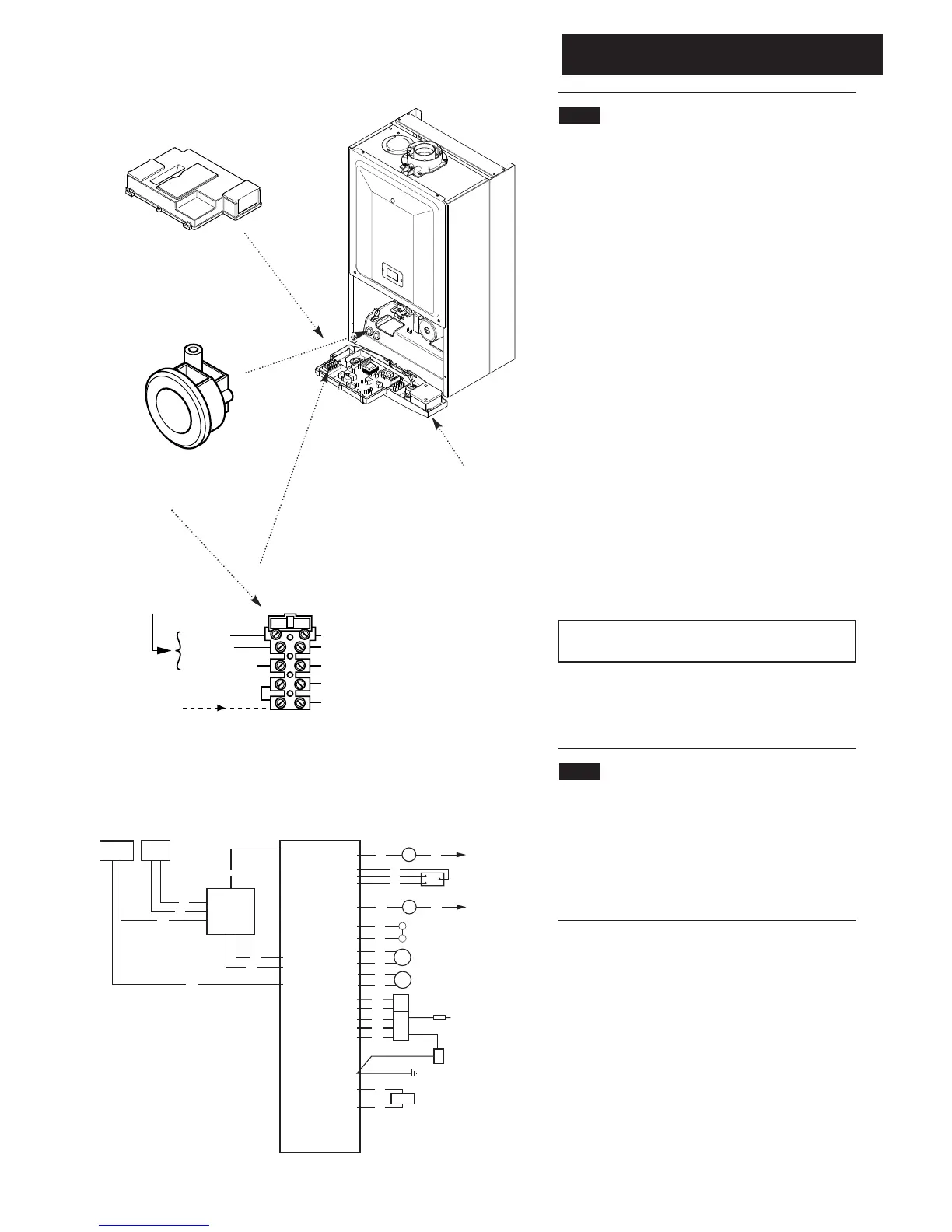
10.8 Making The Electrical Connections
To connect the mains input cable proceed as follows:-
1. Slacken the facia securing screws and lift the outercase
panel so that its securing tabs are clear of the facia. Remove
the panel.
2. Completely undo the screws securing the facia panel and
hinge it down (Fig. 39).
3. Remove the control box cover securing screws.
Disengage the barbs on the control box from the cover.
Remove the cover (Fig. 40).
4. Slacken the cable clamp on the LH side of the boiler
chassis (Fig. 41). Insert the cable through the clamp and
route it to the terminal block.
5. Slacken the screws in the terminal block, connect the
input cable, and tighten the screws.
6. Run the input cable from any external control through
the second cable clamp on the boiler chassis. Refer to the
instructions supplied with the control.
7. To connect external control(s) remove the link between
terminals 1 & 2. The switched output from the external
control must be connected to terminal 2 (Fig. 42).
IMPORTANT: The external control MUST be suitable for
230V switching and fused 3A maximum
8. Ensure that both mains input and any external control
input cables have sufficient slack to allow the control box to
drop down. Tighten the cable clamp(s) on the boiler chassis.
10.9 Preliminary Electrical Checks
1. Prior to commissioning the boiler preliminary electrical
system checks should be carried out.
2. These should be performed using a suitable meter, and
include checks for Ground Continuity, Resistance to
Ground, Short Circuit and Polarity.