8
2.0 General Layout
© Baxi Heating UK Ltd 2007
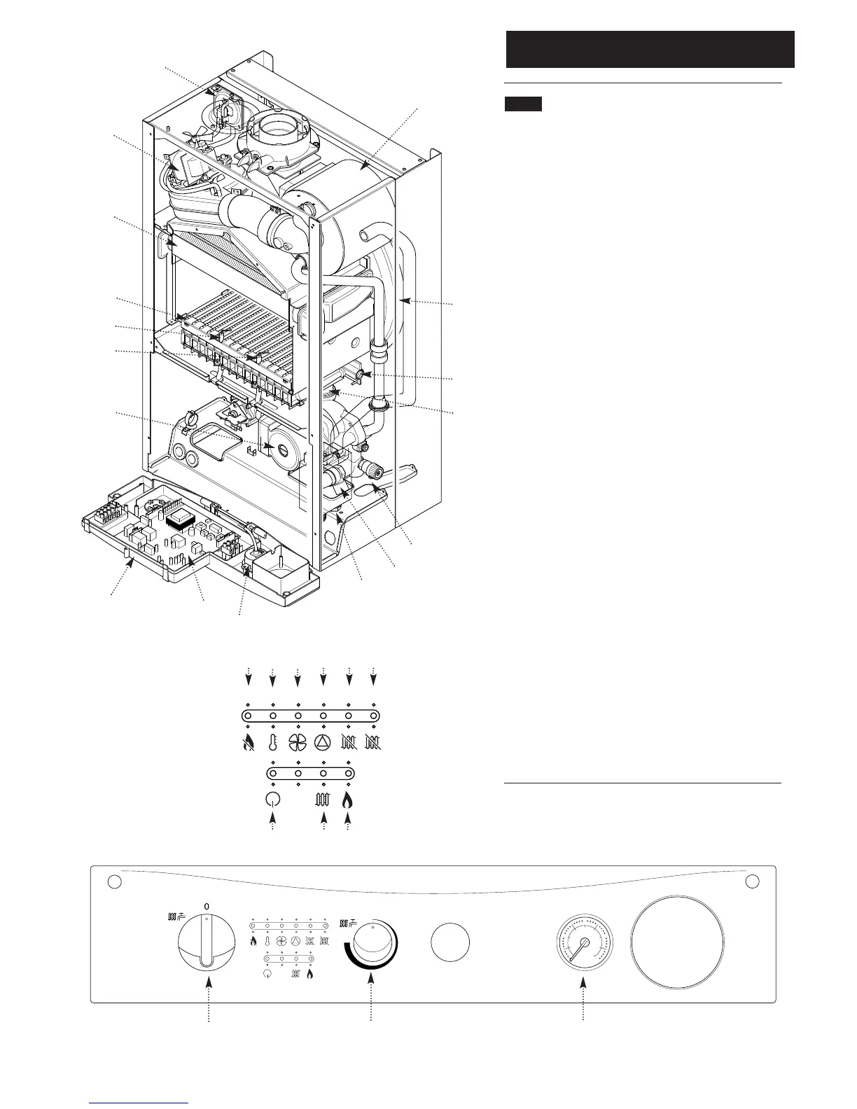
2.1 Layout
1. Air Pressure Switch
2. Expansion Vessel
3. Burner Manifold
4. Automatic Air Vent
5. Circulation Pump
6. Drain Off Point
7. Pressure Relief Valve
8. System Pressure Gauge
9. PCB
10. Control Box
11. Condensate Trap
12. Flame Sensing Electrode
13. Spark Electrode
14. Burner
15. Primary Heat Exchanger
16. Fan Assembly
17. Secondary Heat Exchanger
18. On/Off/Reset Selector Switch
19. Temperature Control
20. Flame Failure or Blocked Condensate Drain
21. Safety Thermostat Activated (Boiler or Flue)
22. Fault on Fan or Flue
23. Fault on Pump or Low System Pressure
24. Fault on Temperature Sensor
25. Fault on Temperature Sensor
26. Power On
27. Boiler On
28. Burner On
When neons 20 to 25 are constantly illuminated, they
indicate the temperature of the central heating water.
16
15
14
11
12
13
10
9
8
18
19
8
6
5
3
4
7
2
1