EasyManua.ls Logo

Bender ISOMETER iso685 -CN Series User Manual

Bender ISOMETER iso685 -CN Series
8 pages
To Next Page IconTo Next Page
Page #1 background imageLoading...
Page #1 background image
1
快速操作手册 / Quick-start guide
CN EN
Insulation monitoring device
This quick-start guide applies to the following devices: iso685-D-
CN, W-D-CN, -S-CN, W-S-CN, D-B-CN, S-B-CN, W-S-B-CN, -D-P-CN,
W-D-P-CN, -S-P-CN, W-S-P-CN. Devices with the suffix -S do not
have a display and therefore need an external display. The opera-
tion is similar to the corresponding iso685 variants with display.
This quick-start guide does not replace the operating manual,
which can be found on our homepage under www.bender.de/
manuals.
Intended use
The ISOMETER® monitors the insulation resistance of unearthed
AC/DC main circuits (IT systems) with mains voltages of AC, AC/
DC 0…690 V or DC 0…1000 V.
DC components existing in AC/DC systems do not influence the
operating characteristics. A separate supply voltage allows de-
energised systems to be monitored. The maximum permissible
system leakage capacitance is 1000 μF, dependent on the appli-
cation-specific profile.
Safety instructions
Risk of electric shock!
The terminals carry high voltage and direct contact with
these terminals will likely result in electrocution. If the
terminals L1/+, L2, L3/- of the device are connected to a
live IT system, the terminals E and KE must not be
disconnected from the protective conductor (PE).
Risk of damage to property due to incorrect
installation!
Connecting more than one insulation monitoring de-
vice may result in damage to the installation. In addi-
tion, the device will not function and will not report an
insulation fault if more than one insulation monitoring
device is connected.
DANGER
CAUTION
绝缘监视仪
这本快速入门指南适用于下列型号 : iso685-D-CN, W-D-CN,
-S-CN, W-S-CN, D-B-CN, S-B-CN, W-S-B-CN, -D-P-CN, W-D-
P-CN, -S-P-CN, W-S-P-CN. 设备带有 -S 后缀的没有显示,
此需要一个外部显示设备。操作类似于对应的带有显示iso685
变形。
这本快速入门手册不能替代操作手册。你可以在我们的主页
www.bender.de/manuals 上找到操作手册。
使用目的
ISOMETER® 监视不接地交直流主回路(IT 系统)的绝缘电阻,
主回路电压 AC, AC/DC 0…690 V 或 DC 0…1000 V。
出现在 AC/DC 系统中的直流组件不会影响操作特性。独立的电
源电压允许断开被监视系统。最大允许的系统泄露电容是1000
µF, 这取决于应用特定的配置。
安全介绍
电击危险 !
端子携带高电压并且直接接触端子可能会导致触
如果设备的端子直接连接到通电的 IT 系统 ,
端子 E KE 不必从 PE 线断开
由于安装不正确而导致损坏的风险 !
连接多个绝缘监视仪可能会导致安装损坏
此外,
如果连接超过一台绝缘监视仪,设备将不起作用
并不会发出绝缘故障警报
108 mm
110 mm
m
m
39
IT-System
1x
1/2
1x
Iso.FehlersucheIso.Fehlersuche
43 s
PGH ON
IT System
OK
230 kΩ
R(an) 40kΩ/10kΩ
OK
230 kΩ
iso685(W)-D, iso685(W)-D-B-CN
iso685(W)-D-P-CN:
绝缘故障定位 /insulation fault locati
危险
警告
ISOMETER® iso685...-CN
iso685_D00022_06_Q_CNEN/10.2016
CN EN
Question and Answer IconNeed help?

Do you have a question about the Bender ISOMETER iso685 -CN Series and is the answer not in the manual?

Bender ISOMETER iso685 -CN Series Specifications

General IconGeneral
Automatic adaptation to system leakage capacitanceyes
Two separate response valuesYes
Self-monitoringYes
Connection monitoringYes
Automatic function testYes
DisplayLCD
Multilingual menu navigationYes
RS-485 interfaceYes
Modbus RTUYes
Galvanically isolatedYes
Housing materialPlastic
Insulation monitoring forAC, DC, and mixed AC/DC systems
Measuring voltageDC
Response valueAdjustable
Power supplyAC/DC 24...230 V
Storage temperature range-40 °C…+70 °C
Relative humidity< 95 % rel. humidity, non-condensing
Protection classIP30 (housing), IP20 (terminals)

Summary

Insulation Monitoring Device Overview

Intended Use

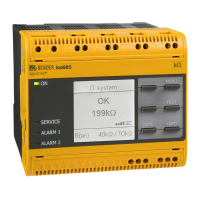
Describes the purpose of the ISOMETER® to monitor insulation resistance in unearthed AC/DC main circuits.

Safety Instructions

Provides critical safety warnings regarding electric shock and incorrect installation risks.

Installation and Connection

Disconnecting from IT System

Instruction to disconnect the device from the IT system before performing tests.

Mounting Options

Details DIN rail and screw mounting procedures, including minimum distances.

Wiring and Electrical Safety

Covers device wiring, terminal connection, and essential safety precautions for electric shock and short circuits.

Wiring Diagram and Terminal Legend

Wiring Diagram Details

Presents the electrical wiring diagram for the ISOMETER® and example wiring configurations.

Terminal Function Legend

Explains the purpose and connections for each terminal on the device.

Device Commissioning

Initial Setup Procedure

Guides through the initial commissioning process, including self-test and wizard setup.

Commissioning with EDS Modules

Details the process for commissioning ISOMETER® with additional EDS modules, including bus address configuration.

Alarms, Effects, and Technical Data

Alarm Causes and Reset

Explains the causes of alarms, device signals, and the procedure for resetting alarm messages.

Technical Specifications

Provides detailed technical data including insulation coordination, voltage, system, response values, and interfaces.

Switching Elements and Compliance

Switching Element Details

Specifies the characteristics of the device's switching elements, including operating principle and endurance.

Other Specifications and Standards

Covers EMC, protection degrees, and compliance with relevant standards like IEC 61557.

Quick-Start Guide Validity

Lists the device models for which this quick-start guide is applicable.

Related product manuals