5
iso685_D00022_06_Q_CNEN/10.2016
ISOMETER® iso685...-CN
报警和它的影响
报警的原因
• 绝缘故障
绝缘电阻有下列 2 组响应值
LEDs ALARM 1 ALARM 2
闪烁。
• 设备故障
LED SERVICE 闪烁。
• 激活绝缘故障定位
LED PGH ON 在故障电流通道闪烁。
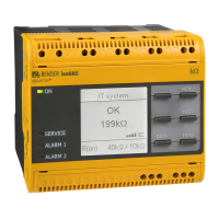
设备信号报警或设备故障
• 显示指示的错误以及应用的测量值。
• 在发生 "ALARM 1" 或 "ALARM 2" 的情况下,相关 LED 等闪
烁。
• 如果分配,会间隔发出报警哔哔声。
• 开关分配的报警继电器。
• 开关分配的数字输出。
重置报警信息 ( 重置 )
要求 : 不再存在报警的原因。 绝缘电阻必须至少高于响应值
25 % 。
选择 : "RESET" > "RESET" > "OK".
技术数据
( )* = 出厂设置
绝缘协调性 (IEC 60664-1/IEC 60664-3)
额定电压
.......................................................................................................................................... 1000 V
过电压分类 (OVC).................................................................................................................................III
额定脉冲电压 (IEC 60664-1) ....................................................................................................... 8 kV
额定绝缘电压 (IEC 60664-1) .................................................................................................. 1000 V
污染等级 (U
n
< 690 V) .......................................................................................................................... 3
污染等级 (U
n
< 1000 V) ........................................................................................................................ 2
保护隔离介于 (≤ 2000 m NN) 和 .........................................................(L1/+,L2,L3/-) 之间 –
........................................................................ (A1,A2) – (11,12,14) – (21,22,24) – (E, KE), (X1, ETH, X3, X4)
电压测试、常规测试 (IEC 61010-1) .......................................................................... AC 2.2 kV
电源电压
电源电压范围 U
s
.................................................................................................. AC/DC 24…240 V
U
s
的公差 ............................................................................................................................. -20…+15 %
U
s
的频率范围 ........................................................................................................... DC, 50…400 Hz
功耗,典型地 50 Hz (400 Hz)...........................................................≤12 W/21 VA (≤12 W/45 VA)
被监视的 IT 系统
标称系统电压范围
U
n
.................................................................. AC 0…690 V, DC 0…1000 V
U
n
的公差 ..............................................................................................................................AC/DC +15 %
U
n
的频率范围 ............................................................................................................. DC, 1…460 Hz
响应值
响应值
R
an1
(Alarm 1) ......................................................................................... 1 kΩ…10 MΩ (40 kΩ)*
响应值 R
an2
(Alarm 2) ......................................................................................... 1 kΩ…10 MΩ (10 kΩ)*
操作的不确定性 ( 符合 IEC 61557-8)...................相关的配置 , ±15 %, min. ±1 kΩ
时间相应
响应时间
t
an
在 R
F
= 0.5 x R
an
(R
an
= 10 kΩ) 和 C
e
= 1 μF
符合 IEC 61557-8 .............................................................................. 相关的配置 , 典型 4 s
测量回路
测量电压
U
m
................................................................................. 相关的配置 , ±10 V, ±50 V
测量电流 I
m
.................................................................................................................................≤ 403 μA
内部电阻 R
i
, Z
i
.............................................................................................................................≥ 124 kΩ
允许外部直流电压 U
fg
.....................................................................................................≤ 1200 V
允许系统泄露电容 C
e
............................................. 取决于相关配置 , 0…1000 μF
接口
现场总线 : 接口 / 协议
....................................................... web server/Modbus TCP/BCOM
Alarm and its effect
Cause of the alarm
• Insulation fault
The insulation resistance is below both response values
LEDs ALARM 1 and ALARM 2 flash.
• Device error
LED SERVICE flashes.
• Active insulation fault location
LED PGH ON blinks according to the locating current.
Device signals alarm or device error
• Display indicates error and, where applicable,
the measured value.
• In the event of "ALARM 1" or "ALARM 2", the associated LEDs
flash.
• A warning sound beeps at intervals, if assigned.
• Assigned alarm relays will switch.
• Assigned digital outputs will switch.
Reset alarm messages (Reset)
Requirement: The cause of the alarm is no longer present. The in-
sulation resistance must be at least 25 % higher than the re-
sponse value.
Select: "RESET" > "RESET" > "OK".
Technical data
( )* = factory setting
Insulation co-ordination (IEC 60664-1/IEC 60664-3)
Rated voltage ............................................................................................................................................. 1000 V
Overvoltage category (OVC) ...............................................................................................................................III
Rated impulse voltage (IEC 60664-1) .......................................................................................................... 8 kV
Rated insulation voltage (IEC 60664-1) ................................................................................................... 1000 V
Pollution degree (U
n
< 690 V) .......................................................................................................................... 3
Pollution degree (U
n
< 1000 V) ........................................................................................................................ 2
Protective separation (≤ 2000 m NN) between......................................................................(L1/+,L2,L3/-) –
........................................................................ (A1,A2) – (11,12,14) – (21,22,24) – (E, KE), (X1, ETH, X3, X4)
Voltage test, routine test (IEC 61010-1) ............................................................................................. AC 2.2 kV
Supply voltage
Supply voltage range U
s
....................................................................................................... AC/DC 24…240 V
Tolerance of U
s
............................................................................................................................. -20…+15 %
Frequency range of U
s
............................................................................................................. DC, 50…400 Hz
Power consumption typically 50 Hz (400 Hz).................................................. ≤12 W/21 VA (≤12 W/45 VA)
IT system being monitored
Nominal system voltage range U
n
..................................................................... AC 0…690 V, DC 0…1000 V
Tolerance of U
n
...............................................................................................................................AC/DC +15 %
Frequency range of U
n
............................................................................................................... DC, 1…460 Hz
Response values
Response value R
an1
(Alarm 1) .................................................................................... 1 kΩ…10 MΩ (40 kΩ)*
Response value R
an2
(Alarm 2) .................................................................................... 1 kΩ…10 MΩ (10 kΩ)*
Operating uncertainty (acc. to IEC 61557-8)...................................... profile-dependent, ±15 %, min. ±1 kΩ
Time response
Response time tan at R
F
= 0.5 x R
an
(R
an
= 10 kΩ) and C
e
= 1 μF
acc. to IEC 61557-8 .................................................................................................. profile-dependent, typ. 4 s
Measuring circuit
Measuring voltage U
m
.................................................................................. profile dependent, ±10 V, ±50 V
Measuring current I
m
.............................................................................................................................≤ 403 μA
Internal resistance R
i
, Z
i
..........................................................................................................................≥ 124 kΩ
Permissible extraneous DC voltage U
fg
.................................................................................................≤ 1200 V
Permissible system leakage capacitance C
e
........................................ dependent on the profile, 0…1000 μF
Interfaces
Field bus:Interface/protocol.............................................................................. web server/Modbus TCP/BCOM
 Loading...