T M
Document NAE2028421 • 07.2016 • © Bender Inc. • Page 1/1 • Side 1/2Bender Inc. • USA: 800.356.4266 / 610.383.9200 / medical@bender.org • Canada: 800.243.2438 / 905.602.9990 / info@bender-ca.com • www.bender.org
LIM2010
Installation Bulletin / Reference Guide
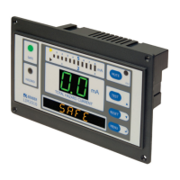
This document is intended as a reference guide to installing and setting a BENDER LIM2010 Line Isola-
tion Monitor. This document includes installation instructions and typical front plate display indica-
tions of the device. For complete details, including installation, setup, settings, and troubleshooting,
refer to the LIM2010 user manual.
Only qualied maintenance personnel shall operate or service this equipment. These instructions
should not be viewed as sucient for those who are not otherwise qualied to operate or service this
equipment. This document is intended to provide accurate information only. No responsibility is as-
sumed by BENDER for any consequences arising from use of this document.
Installation
Mounting
The front plate provides four holes with a diameter of 1/8” (3.2 mm) for screw mounting. Use
the four (4) provided screws for mounting. Use minimum 2.6 lb-in (0.3 N-m), maximum 3.5 lb-
in (0.4 N-m) torque. Before mounting, plug the connector plate into the LIM. Refer to Figures 1
and 2 for dimensions, listed in inches (mm).
Wiring
The LIM2010 connects to a connector plate assembly. Use the proper wiring diagram to con-
nect to the assembly. Before mounting the LIM, plug the connector plate into the LIM.
Figure 4 shows wiring the connector plate for basic in-
stallation with no accessories. If other equipment is to
be installed, such as remote indicators, fault location, or
load monitoring, or for more information on the con-
nector plate and installation, refer to the LIM2010 user
manual.
Connector plate L1 and L2 connect to the main lines
of the system, on the secondary of the isolation trans-
former. Connector plate LIMGND and GND2 are sepa-
rate connections to the system ground.
!
DANGER
• Disconnect all power before servicing.
• Reference NFPA 99 / CSA Z32 for
Installation Standard.
HAZARD OF ELECTRIC SHOCK,
EXPLOSION, OR ARC FLASH
4” (101.5)
7” (177)
6.5” (164)
4.4” (112)
5.3” (134.5)
2.4” (62)
3.1” (79.5)
Figure 1 - LIM2010 dimensions, front view Figure 2 - LIM2010 dimensions, rear isometric view
Figure 3 - Connecting connector plate plugs to LIM2010
L1
L2
GND
Figure 4 - LIM2010 connector plate wiring - basic installation with no accessories
Connector Plate
Actual cable length for connector cables is 20” (50.8 cm). Both plugs are connected to
LIM2010. Connector plate must only be installed in a grounded, metallic enclosure.
Figure 5 - CP-LIM2010 connector plate
Connector plate terminals
Type Description
L1, L2 Connected to secondary of isolation transformer
12 VDC Com. Common connection for remote indicators
A, B RS-485 communication interface
RI1 Test button source for remote indicators
K1/NC Alarm relay K1, N/C
K1/Common Alarm relay K1, common
K1/NO Alarm relay K1, N/O
SAFE "SAFE" light connection for remote indicators
HAZARD "HAZARD" light connection for remote indicators
RI2 Local and system muting from LIM and remote indicators
GND2, LIM GND Separate ground connections
TEST Connection for remote test
Z1/M+, Z2/M- Connection for overtemperature sensor or analog meter
K2/Common Alarm relay K2, common
K2/NC Alarm relay K2, N/C
K2/NO Alarm relay K2, N/O