Do you have a question about the Bender A-ISOMETER IRDH275 and is the answer not in the manual?
Defines the intended use of the A-ISOMETER® and liability exclusions.
Outlines warranty exclusions for damage caused by misuse, incorrect installation, or unauthorized modifications.
Lists common features like IT system monitoring, extended voltage range, AMPPlus principle, and self-test.
Highlights features specific to the IRDH275B, such as memory, BMS interface, and current output.
Provides a step-by-step flow chart for commissioning the device, starting with system type and voltage checks.
Continues the commissioning flow chart, covering supply voltage, clock setting, and basic setting checks.
Completes the commissioning flow chart, focusing on functional tests with resistances and checking alarm outputs.
Details wiring instructions for connecting the A-ISOMETER® to the supply voltage and protective devices.
Illustrates how to connect external coupling devices to extend the device's voltage range.
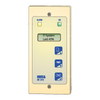
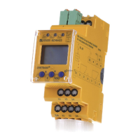
Introduces the device's operating elements, displays, and function keys.
Details the functions assigned to each key (INFO, TEST, RESET, MENU) and their roles in operation.
Explains how to navigate the menu system, change parameters, and switch between modes.
Explains how to select and store response values for Alarm 1 and Alarm 2.
Describes the settings for alarm relays K1 and K2, including N.O, N.C, and flashing functions.
Describes the configuration for external coupling devices (AGH) to extend voltage ranges.
Covers leakage capacitance adaptation, measuring principle, self-test settings, and clock/date configuration.
Explains how to set the unique BMS bus address for the IRDH275B to avoid conflicts.
Details activating and configuring the ISOnet function for scanning and controlling slave devices.
Explains how to activate and set a password to protect the device from unauthorized changes.
Presents key technical specifications of the IRDH275(B) in a tabular format.
| Type | Insulation monitoring device |
|---|---|
| Automatic adaptation to system leakage capacitance | Yes |
| Two separate response values adjustable | Yes |
| N/O or N/C operation selectable | Yes |
| Automatic device self test | Yes |
| Connection monitoring (L1-L2-PE) | Yes |
| Two independent alarm relays with separate terminals | Yes |
| Modbus RTU interface | Yes |
| Approvals | CE, UL, CSA |
| Storage temperature | -40°C to +70°C |
| Display | LCD |
| Operating temperature | -20…+60 °C |
| Measuring Range | 1 kΩ to 10 MΩ |
| Supply voltage | 24 V DC or 110-230 V AC |
| Power supply | 24 V DC or 110-230 V AC |


 Loading...