Do you have a question about the Bender A-Isometer IRDH 275 and is the answer not in the manual?
Defines the intended use of the insulation monitoring device.
Details warranty exclusion conditions and manufacturer liability.
Provides guidance on installing the insulation monitoring device correctly.
Lists shared and specific features of IRDH275 and IRDH275B models.
Details extra functions available for the IRDH275B model.
Instructions for connecting the A-ISOMETER® terminals to the supply voltage.
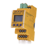
Describes the operating elements and displays of the IRDH275(B).
Explains the functions assigned to each button on the device.
Describes how to select response values for Alarm 1 and Alarm 2.
Explains the N/O and N/C operation of alarm relays K1 and K2.
How to set the BMS bus address for the IRDH275B.
How to activate and set a password for device protection.
Details data transmission and requirements for IsoData protocol.
Step-by-step guide for commissioning an RS485 network with BMS protocol.
Presents technical specifications in a tabular format.
Lists available A-ISOMETER® types, voltage ranges, and article numbers.
| Insulation monitoring device for unearthed AC and DC systems | Yes |
|---|---|
| Response value range | 1 kΩ...10 MΩ |
| Separate test button | Yes |
| Connection monitoring (L, N, PE) | Yes |
| Two separately adjustable response values | Yes |
| Two changeover contacts | Yes |
| Fault memory with adjustable reset delay | Yes |
| RS-485 interface | yes |
| Device version with Modbus RTU | Yes |
| Graphical display | Yes |
| Display of the insulation resistance | Yes |
| Display of the system voltage | Yes |
| Display of the earth leakage capacitance | Yes |
| History memory | Yes |
| Measurement range | 1 kΩ...10 MΩ |
| Protection class | IP30 |
| Supply voltage | 24 V DC |
| Measuring voltage | 12 V |
| Display | Graphical |
| Power supply | 24 V DC, 85...230 V AC/DC |


 Loading...